Your task is to design, build, and test an amplifier for an ultrasonic receiver which can detect a signal from at least 2 meters away. Then modify this system to reliably detect an on/off modulated ultrasonic signal from as far away as possible.
1. Description
-
2 Vp-p output at 2m distance
- Required decisions
-
How much voltage gain is enough?
-
Which op amp to use?
-
How many amplifier stages?
Some of these questions can only be addressed with thoughtful experimentation.
2. Helpful information
2.1. Inverse square law
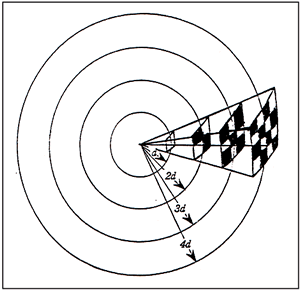
Consider a finite amount of sound intensity (power per area, W/m2) leaving a speaker and a virtual sphere of diameter d centered at the speaker having a small patch on it which collects all energy pasing through the patch’s area. See Figure 1, “Inverse square law setup” for an illustration. A certain fraction of the total sound power emitted from the speaker will be absorbed by the patch depending on the proportion of the patch’s area to the sphere’s total surface area.
If the patch’s distance is doubled to 2d, the patch’s area must be increased by a factor of \(\left(\frac{2d}{d}\right)^2\) (4x) in order to absorb the same power as before. Stated the other way, a (same area) patch at distance d2 will absorb the following power compared with a patch at distance d1:
Since the voltage output of the microphone is proportional to the square root of the power, the relationship may also be expressed as:
→ Doubling of distance reduces received power by 1/4 and a reduction in received voltage by a factor of 1/2.
2.2. 1-pole RC high-pass filter:
2.3. 1-pole RC low-pass filter:
2.4. DC errors
If you make the following assumptions:
-
The open-loop gain Av0 is large enough, which means \(\gg \left(1 + \frac{R_f}{R_1}\right)\)
-
The opamp’s open-loop output impedance Zout is low enough, or much less than the impedance seen by the output node (for this lab = 50,047 Ω).
The total non-inverting opamp output from the input signal and DC errors VOS and (IB, IOS) ←→ (IB+, IB-) is:
-
\(R_{eq+}\) and \(R_{eq-}\) are the impedances seen by the + and - input terminals of the opamp.


References
-
[[[341-notes]]] D. White, ECE 341 Class notes 2019 folder, https://drive.google.com/drive/folders/1vzdLxzTUAC6xXF6YjVcDRuy_BKR7gzDz?usp=sharing
-
[[[341-docs]]] D. White, ECE 341 reference documents folder, https://drive.google.com/folderview?id=0B5O5cSaA0tEQYVpaSnJxMGFrdHM
-
[AoE] P. Horowitz and W. Hill, The Art of Electronics 3rd ed. (affiliate link), Cambridge University Press, 2015. https://artofelectronics.net
-
[L-AoE] T. Hayes, Learning the Art of Electronics: A Hands-On Lab Course (affiliate link), Cambridge University Press, 2016. https://learningtheartofelectronics.com
-
[LEC] Tony R. Kuphaldt, Lessons in Electric Circuits, Source version: https://www.ibiblio.org/kuphaldt/electricCircuits/, All About Circuits version: https://www.allaboutcircuits.com/textbook/
-
[CL-book] Michael F. Robbins, CircuitLab, Ultimate Electronics: Practical Circuit Design and Analysis, https://www.circuitlab.com/textbook/
-
[TCA] Alfred D. Gronner, Transistor Circuit Analysis, Simon & Schuster, 1970, https://archive.org/details/TransistorCircuitAnalysis
-
[CMOS VLSI] Neil Weste and David Harris, CMOS VLSI Design - A Circuit and Systems Perspective, 4th edition. Addison-Wesley, 2011. http://pages.hmc.edu/harris/cmosvlsi/4e/index.html
-
[Guidebook] D. White, Guidebook for Electronics II. https://agnd.net/valpo/341/guidebook
-
[Gummel-Poon] H.K. Gummel, H.C. Poon, An Integral Charge Control Model of Bipolar Transistors. Bell System Technical Journal, 49: 5. May-June 1970 pp 827-852. https://archive.org/details/bstj49-5-827
-
[ROHM] ROHM Semiconductor, Electronics Basics, http://www.rohm.com/web/global/en_index
-
[vishay-e-series] Vishay, Standard Series Values in a Decade for Resistances and Capacitances, https://www.vishay.com/docs/28372/e-series.pdf