Over 35,000,000,000 (billion!) microcontrollers (MCUs) were manufactured last year. Each is a chip that contains a processor, RAM, code storage, and everything else it needs to run programs and interact with the outside world.
Devices with these chips are called embedded systems and are designed and programmed by electrical and computer engineers.
1. Setup
- Hardware
-
-
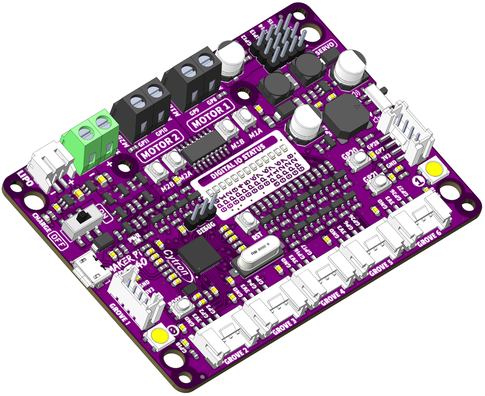
Maker Pi RP2040 development board
-
Servo
-
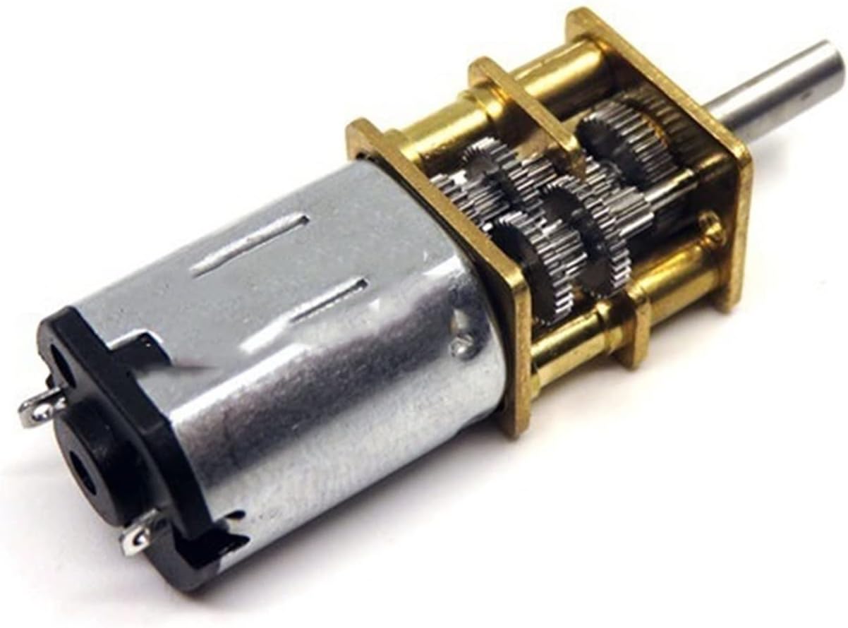
N20 geared motor
-
-
USB-micro data+power cable
-
- Computer
-
-
 Thonny software for editing and downloading code to the board
-
2. DC motor
2.1. Manual control
Let’s first play with the DC motor and make it spin without programming.
The N20 gear motor is a small DC motor with a gearbox that comes in many variations of gear ratios and output shaft options.
If you have used an electronic door lock and heard the whirring sound it makes when locking, it was likely this motor inside.
They have a great combination of speed, torque, and size for small robotics projects.
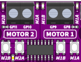
Find the motor terminals and driver chip on your board like in Figure 4.
Connect the motor leads to the MOTOR 1 terminals.
The buttons let us test the motor before we write any code.
-
Push the buttons!
What happens? (click after seeing for yourself)
It jumps when both starting and stopping. This is the effect of Newton’s laws of motion when the motor changes speed suddenly.
-
Push down both
M1BandM1Abuttons at the same time, -
then rock your finger so its only pushing one button.
What is different? (click after seeing for yourself)
It jumps when starting but coasts down instead of stopping suddenly.
buttonM1A |
buttonM1B |
pinGP8 |
pinGP9 |
Motor effect |
|---|---|---|---|---|
up |
up |
0 |
0 |
brake / short |
up |
down |
0 |
1 |
forward |
down |
up |
1 |
0 |
backward |
down |
down |
1 |
1 |
coast / open |
You are seeing the difference between short-circuiting the motor (acting like a brake) and disconnecting the motor (letting it slow down with only friction). The motor driver chip has the transistor switches inside and the input combinations activate the various operational modes.
-
Look at Table 1 and try out the button combinations again.
In an electric vehicle, stepping on the brake pedal first activates the brake mode of the motor controller — it is converting mechanical kinetic energy from the car’s speed back into electrical energy to recharge the battery. Pressing the brake pedal harder will eventually engage the mechanical disc brakes, but it would be a good engineering design if the regenerative braking was used as much as possible.
2.2. Program control
Let’s now “push the buttons” from code instead.
Click the ![]() icon in the upper-right next to
icon in the upper-right next to PYTHON to copy the code to your clipboard.
from time import sleep
import board
import digitalio as dio

# Setup DC motor pins
M1A = dio.DigitalInOut(board.FIXME)
M1A.direction = dio.Direction.OUTPUT

M1B = dio.DigitalInOut(board.FIXME)
M1B.direction = dio.Direction.OUTPUT

# Names are better than numbers
BRAKE    = (0, 0)
FORWARD  = (0, 1)
BACKWARD = (1, 0)
COAST    = (1, 1)

# Sequence of things to do.
commands = (
    FORWARD,
    BRAKE,
    FORWARD,
    COAST,
    BACKWARD,
    BRAKE,
    BACKWARD,
    COAST,
)

while True:
    # walk through each of the actions
    for state in commands:
        print(state)

        # set the motor pins according to the state, M1x.value = 0
        # hint:
        #   a = state[0]
        #   b = state[1]
        # is the same as:
        #   a, b = state

        # FIXME: what is needed here?


        # wait for a bit
sleep(0.5)-
Find the
FIXMEplaces in the code and change them as appropriate.
Take a few minutes to read this code while watching what the motor does,
-
then change the code to do something a little different to understand better.
-
Try doing:
FORWARD,COASTand only sleep for 0.001 seconds? (first comment out theprint(state))
orFORWARD,COAST,COAST? This is how a speed controller works for a DC motor!
Click for more details about mechanical averaging.
- Mechanical averaging
-
The simple “trick” is applying power to the motor then letting it coast really quickly. Even this small motor can’t speed up much when power is applied for 0.001 seconds, but it still does some. After a bunch of pulses the motor eventually is going at a slower speed that is proportional to the ON time percentage. The rotational inertia of the motor is doing the smoothing of those quick pulses while the electronics are hammering the motor with speedup/slowdown commands.
2.3. Pulse-width modulation PWM
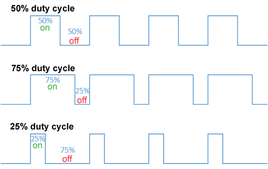
An MCU has special hardware on its chip to easily pulse pins quickly and evenly without needing to manually bit-bang the pins using code. You learn much more about common MCU peripherals in ECE 322 and ECE 422.
This method sets the high time to a fraction (duty cycle) of the repetition time (period), and is called pulse-width modulation (PWM). Remember: frequency = 1 / period.
“Push” the GP20 and GP21 buttons to change the motor’s speed and direction by changing the duty cycle.
from time import sleep
import board
import digitalio

import pwmio
from adafruit_motor import motor

# Initialize buttons as digital inputs
# FIXME: your turn to set up the inputs.  What var names are assumed here and used later?

# DC motor setup
M1A = pwmio.PWMOut(board.GP8, frequency=1_000)
M1B = pwmio.PWMOut(board.GP9, frequency=1_000)
motor1 = motor.DCMotor(M1A, M1B)

# variables to remember our status
speed = 0
last_speed = speed

# always do this
while True:
    # Read buttons' values and change the speed by an increment
    if button1.value == 0:   # button pin is _low_ when pressed!
        speed += 1
        # or speed = speed + 1

    if button2.value == 0:
        speed -= 1
        # or speed = speed - 1

    # FIXME: describe what do these do.  Experiment at the python prompt to test.
    speed = max(speed, -100)
    speed = min(speed, 100)

    if speed != last_speed:  # only update the user if something actually changed
        last_speed = speed
        print(speed)

    # update the motor's speed.
    if speed == 0:
        motor1.throttle = None  # 0 is "brake", None is "coast"
    else:
        motor1.throttle = speed / 100  # need -1.0 to +1.0 instead of a percent

    # Wait before reading the button again
sleep(0.01)-
What happens if you press both input buttons at once? Figure this out from the code and try it out!
Click for more details about the motor’s noises.
- Screaming motors?
-
Remember how the motor is really speeding up and slowing down quickly and not actually moving at a truly constant speed? This is a physical (change in) motion of a thing about 1,000 times per second — which moves the air around it — which is in the middle of a human’s hearing range ⇒ sound! The varying pulse width changes the number and strength of frequencies of N × 1,000 Hz, which is why the sound changes with the speed. You compute these exactly in a junior-level ECE course.
3. Servo
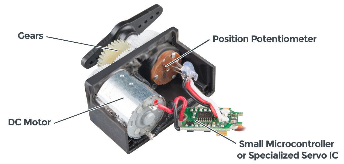

A servo is a combination of a mover and a shaker position sensor with a circuit that figures out how to move to the position commanded at its control input.
Hobby servos take a specific range of pulse widths at a 50 Hz (1 / 50 = 20 ms) refresh rate.
The Maker Pi board has convenient connectors for 4 servos.
It can handle up to 18 by manually wiring to the GPxx pins if you have some crazy ideas.
from time import sleep
import board
import digitalio as dio

import pwmio
from adafruit_motor import servo

# Initialize buttons as digital input.
button1 = dio.DigitalInOut(board.GP20)
# FIXME: fill in the rest.  Something is a little different!

# Create a PWMOut object on the servo's control pin
# Initialize Servo object.
pwm1 = pwmio.PWMOut(board.GP12, duty_cycle=0, frequency=50)
servo1 = servo.Servo(pwm1, min_pulse=580, max_pulse=2700)

# variables to keep track of things
angle = last_angle = 90

# The Main Event ... loop
while True:
    # Read buttons' values to change the angle.
    if button1.value == 0: angle += 1
    if button2.value == 0: angle -= 1

    # Limit the angle from 0 to 180 degrees.
    angle = max(angle, 0)
    angle = min(angle, 180)

    if angle != last_angle:
        last_angle = angle
        print(angle)

    # Command a new servo angle.
    servo1.angle = angle

    # Delay a bit to slow down the button response
sleep(0.01)-
Modify the code to move by 5 degree steps when pressing a button instead.
Click for more things to try.
- Servos fight back
-
Try to turn the servo while its powered up and being sent a position command — it fights back with force. What is happening is: you change the angle a little bit → the control chip notices that the actual angle is different from the commanded angle → the chip drives the motor in the direction to fix this error (at full power!).
Remember which way the connector goes and un-plug the servo. Now try to turn the output shaft. The only resistance now is the friction in the gear train to spin the motor. Such a large gear ratio allows a servo to use a small high-speed motor and still provide lots of torque at the output shaft.
4. Everything
Use the two buttons to control both the DC motor speed and servo position. Deal with the fact that the motor library expects numbers {-1.0 … +1.0} while the servo library expects numbers {0 … 180}.
from time import sleep
import board
import digitalio as dio

import pwmio
from adafruit_motor import servo
from adafruit_motor import motor

# Initialize buttons as digital input.
button1 = dio.DigitalInOut(board.GP20)
button2 = dio.DigitalInOut(board.GP21)
button1.direction = button2.direction = dio.Direction.INPUT

# DC motor setup
M1A = pwmio.PWMOut(board.GP8, frequency=1_000)
M1B = pwmio.PWMOut(board.GP9, frequency=1_000)
motor1 = motor.DCMotor(M1A, M1B)

# Create a PWMOut object for the servo's control pin.
# Initialize Servo objects.
pwm1 = pwmio.PWMOut(board.GP12, duty_cycle=0, frequency=50)
servo1 = servo.Servo(pwm1, min_pulse=580, max_pulse=2700)

# variables for housekeeping
angle = last_angle = 90

# why quit when you're having fun!
while True:
    # Read buttons' values.
    if (button1.value == 0): angle += 1
    if (button2.value == 0): angle -= 1

    # Limit the angle from 0 to 180 degrees.
    angle = min(max(angle, 0), 180)

    # Command a new servo angle.
    servo1.angle = angle

    # convert 0..180 angle range to -1.0 to +1.0 motor range
    speed = (angle - 90)/90
    if speed == 0:   # motor speed = 0 is special, so avoid it
        speed = None

    # update the motor's speed
    motor1.throttle = speed

    # Slow down the update rate so the button effect feels reasonable.
sleep(0.01)5. References
5.1. New to CircuitPython?
Read these in order:
CircuitPython is a modification of MicroPython and is great for learning and short programs.
I usually use MicroPython directly because it makes “driving” the advanced details the MCU in ways that make more sense for me as an expert.
The Maker Pi RP2040 board’s documentation helpfully has examples for both.
You can also program the board using the Arduino tools, or even in bare C or C++ for ultimate control of the software and hardware.
5.3. Thonny install + setup
Download and install Thonny from thonny.org.
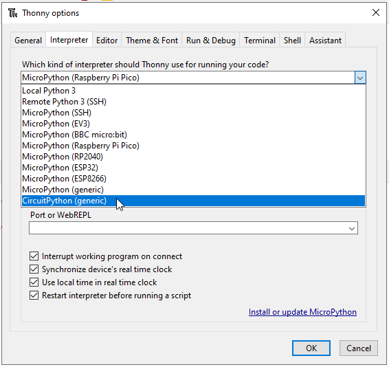
Open Thonny and prepare it for connecting to external boards:
-
[Menu] Tools → Options →
[tab] Interpreter →
[dropdown] Which kind … ? →
[item] CircuitPython (generic)
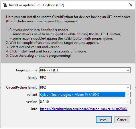
Optional, only needed once:
-
“Install or update CircuitPython (UF2)”. will do as it says.
Select Cytron Technologies - Maker Pi RP2040 from the list to match the purple board. It may be necessary to exit the Thonny options window and then open it again to refresh the list items.
-
[Menu] View → [check] Files
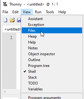
-
Close Thonny, ensure the board is connected, then re-open Thonny
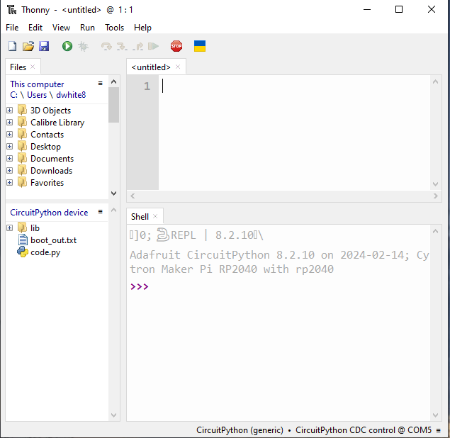
You now are ready to copy-paste the examples in this activity.
| The stop button is sometimes needed to re-connect with the board. |