Faraday says that changing magnetic flux induces a voltage, let’s see this!
1. Setup
2. Procedure
2.1. Build initial circuit

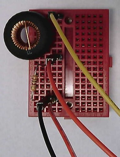
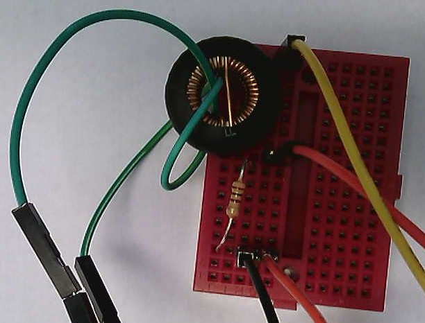
Construct the circuit of Figure 1 so it looks similar to Figure 2. Oscilloscope input channel 1 is shown measuring the voltage across R1 in the picture. This setup allows you to measure:
-
Inductor voltage
-
Inductor current (by Ohm’s law)
-
Wavegen #1 signal voltage
Setup the waveform generator with the following configuration:
-
square
-
100 kHz
-
1 Vp-p
Attach the input channels so that your scope displays:
-
Inductor voltage.
-
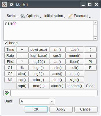
Inductor current. Do this by adding a Math ("Custom") display that computes
Cx/100wherexis the channel you have measuring VR. See Figure 3 — be sure to change the units!
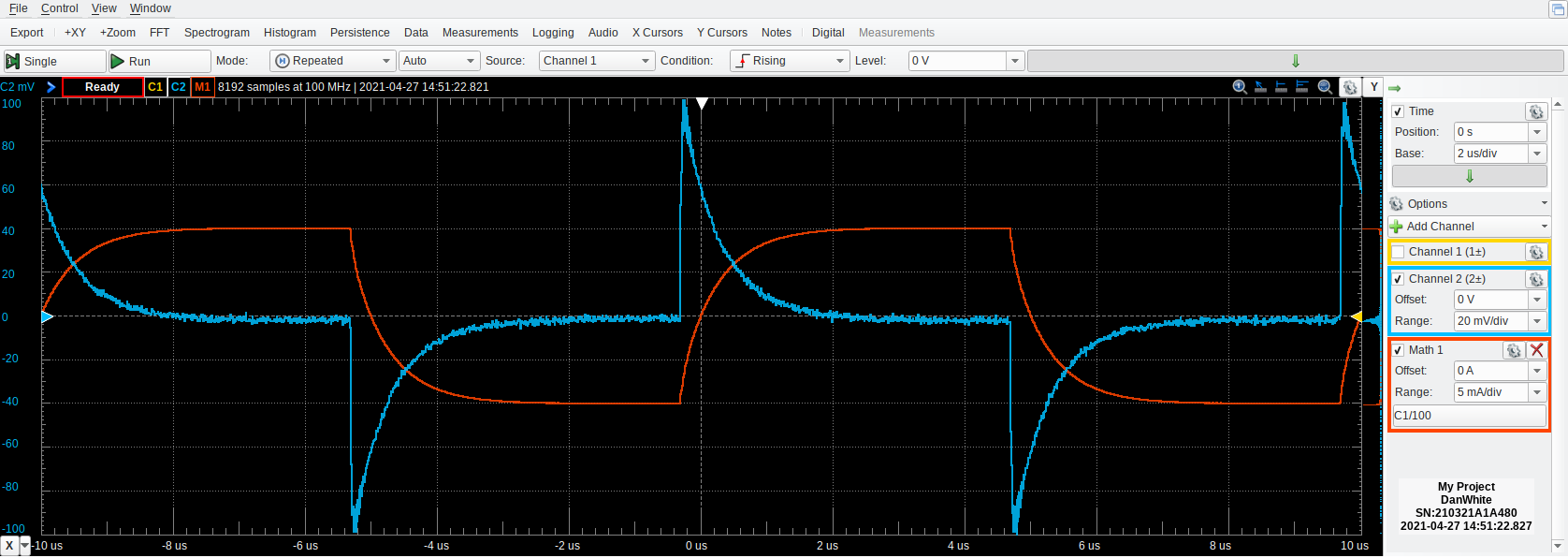
Carefully look at the two (voltage and current) waveforms associated with this inductor.
-
Relate the displayed waveforms to the inductor equation relating voltage to current.[1]
You should be able to make a reasonable estimate of the inductance from the time-domain waveforms. Describe your measurements, calculations, and result.
2.2. Coupled magnetic field
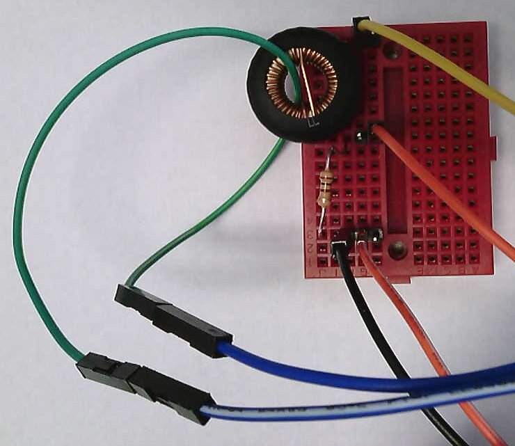

Now thread a wire through the center of the inductor as shown in Figure 4. The schematic view of this setup in Figure 5 reminds you that you now have two inductors which share some portion of their magnetic fields. This is measured either as M mutual inductance or k coupling coefficient.
Change your scope inputs to measure the current through the L1 inductor and the voltage across the inductor (the added wire) Loop. The current flowing through L1 generates a magnetic flux (the many turns of wire increase the generated flux by N for the same current). The other wire (green in the picture) intercepts this flux. Because the flux is changing, Faraday’s law says that there is a voltage induced across the second coil that is proportional to the derivative of this magnetic flux.
-
Figure 5 includes a dot for one of the inductors. Experimentally determine which end of your loop has the dot by carefully considering the polarities of the L1 current, the polarity of the Loop voltage, and the direction of the windings (remember the right-hand rule).
|
Carefully keep track of which end is which for both inductors! Draw and annotate sketches of your setup to help keep the orientations straight. |
2.3. Adding loops
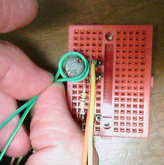
Add a second turn to your coupled inductor by passing your wire through the center of L1 again similar to Figure 7.
| This coil has two complete turns. The connection to the scope input completes the full turn. |
-
Determine the relationship between the coil’s induced voltage (peak-to-peak is a good metric) and the number of turns.
Plot this relationship!
3. Submission
Write a report that describes your lab setup. It must inclue discussion about each of the [ ] checkbox items.
Include:
-
schematics representing each setup
-
pictures of the physical setup
-
documentation of all your measurements, including units
-
mathematical work as needed
Discussion engineering style involves measurements, math, and numbers and provides reality and observation-based reasoning for claims; no "truth by assertion."