1. Hand analysis and plotting videos
-
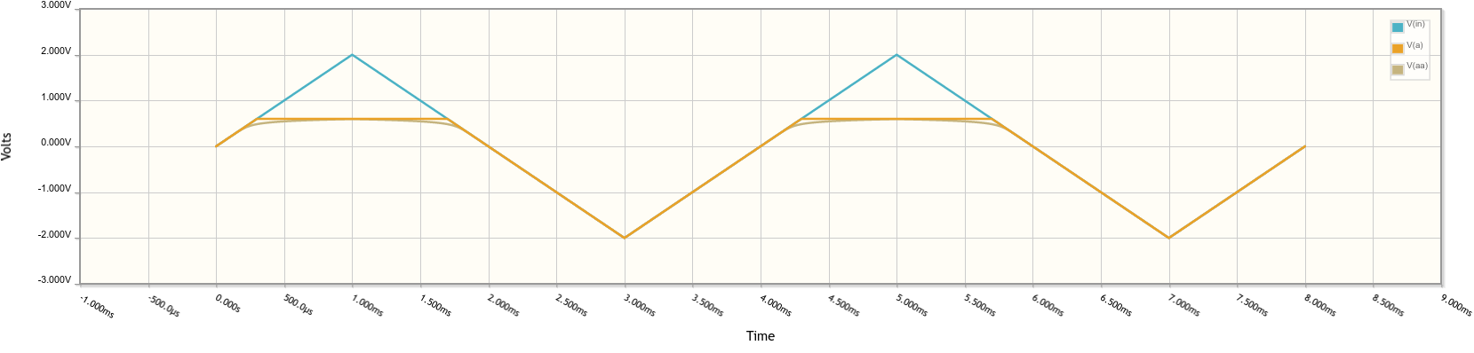
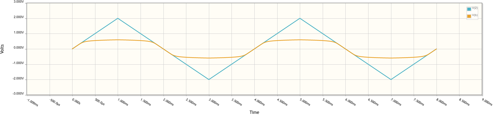
Circuits A and B: Diode circuit waveforms, part 1
-
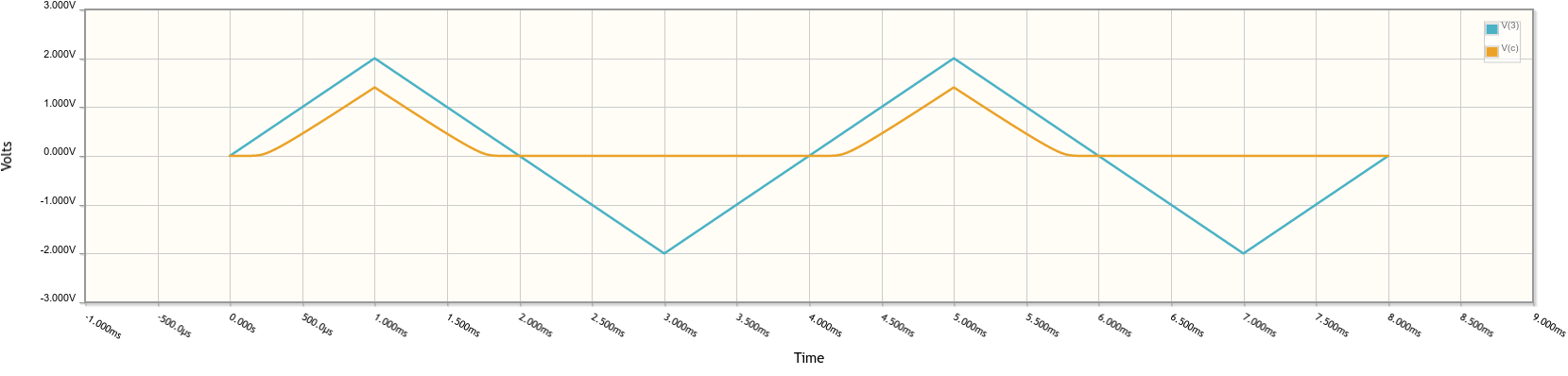
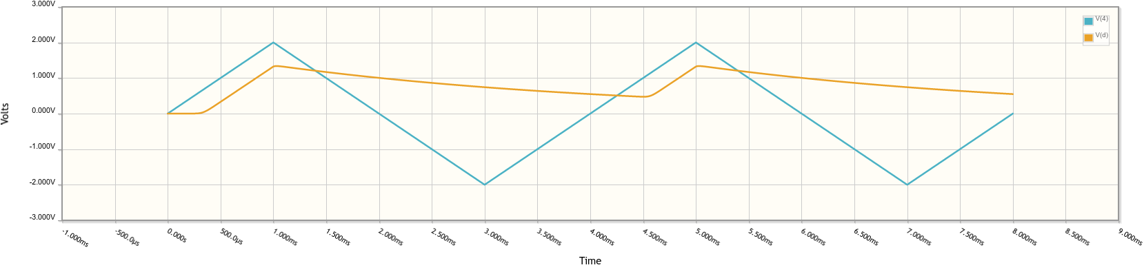
Circuits C and D: Diode circuit waveforms, part 2
2. Class time
2.1. Review hand calc process
From day12
-
Example 2 (instructor)
-
Example 3 (students)
-
Example 4 (students)
2.2. Simulator solution
Open CircuitLab
-
Draw and solve the circuits of day12 Examples 1, 2, 3, 4
Open this CircuitLab schematic, the same as the diode waveforms handout:
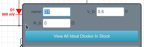
Double-click on D1 and D1a to see the parameters that are configured.
-
D1 is CircuitLab’s “ideal diode”, and behaves the same way as the ideal or constant-voltage models from the color figure depending on the value set for
V_D. -
D1a is set to the default realistic diode model for a 1N4148.
-
Hover over the nodes and you will notice that everything is 0 V. This is because the DC solver is using the t = 0 seconds value for the voltage sources, which is 0 V.
-
Click the Simulate button near the lower left corner.

2.3. Time-domain simulation
The simulation is already configured to run a Time Domain simulation from 0 to 10 ms with a time step of 10 μs.
-
PSpice, LTspice, and most other simulators call this a Transient analysis.
-
YOU must choose a good value for the Time Step!
-
Too large of a step gives bogus and misleading results.
-
Choose a small enough time step so that the waveform has enough samples to trace an accurate shape of the “fastest” edges in your circuit.
-
Too small of a step means that the simulator needs to compute a TON of points … which can take a long time.
-
How many time steps will the simulator compute in this situation?
-
What happens if
Time Step == (Stop Time - Start Time)?
The node voltages to plot are already configured.
2.4. Run the simulation
-
Run the simulation, which opens the waveform data plot.
-
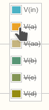
Deselect all of the waveforms except for V(in).
-
Add back V(a).
The V(a) waveform is an exact match to the hand analysis solution! This is a great way to check your hand drawings!
-
Add V(aa) also, then remove V(in) so you only see the two Circuit A waveforms.
-
Is 0.6 V a good choice for \(V_{D,\mathrm{on}}\) in this particular circuit?
-
Is there a one-true-best value for \(V_{D,\mathrm{on}}\)?
-