1. Supplies
-
your Analog Discovery 3 with accessories (USB cable).
-
Benchtop oscilloscope, Keysight MSOX-2004, in GEM 166.
-
Two oscilloscope cables.
2. Procedure
2.1. Preliminary comments
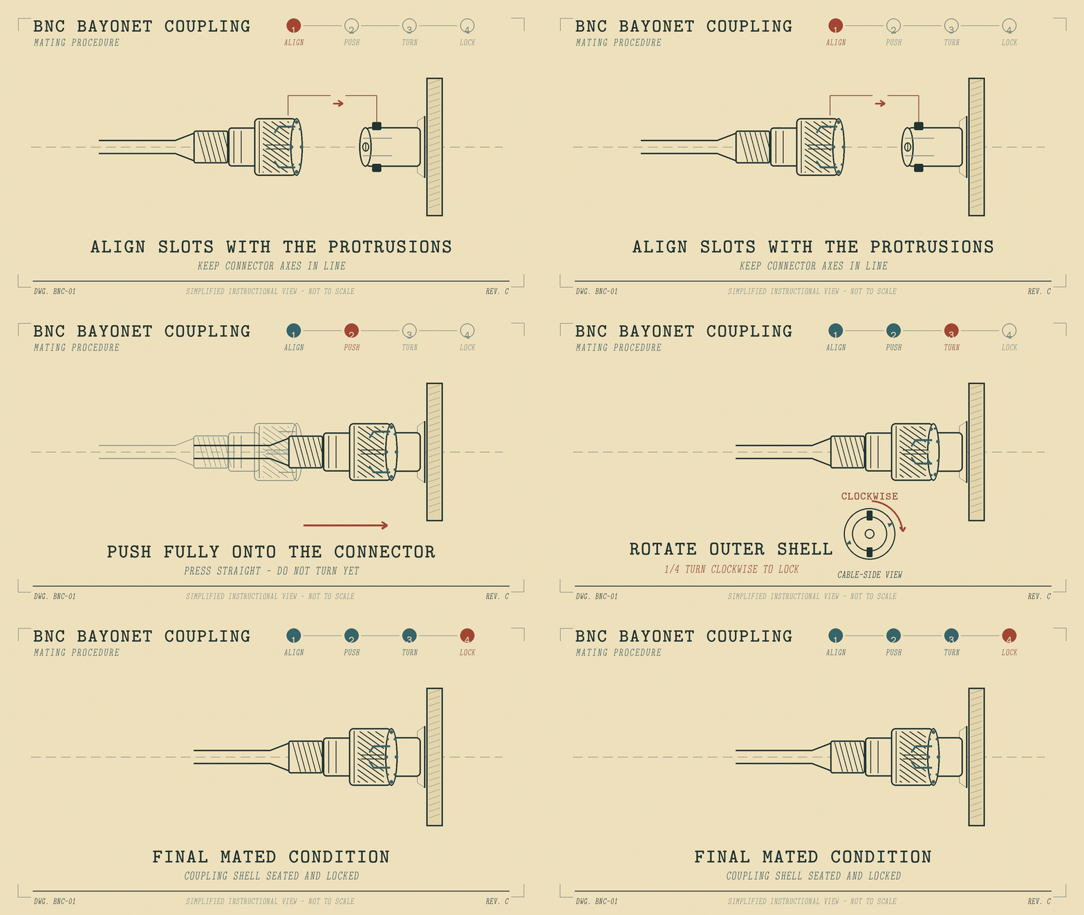
The BNC type connector has a locking ring that keeps the connector from pulling out. Oscilloscope probes nearly always use BNC-type connections to the oscilloscope, but the twist-lock slot is frequently hidden under a plastic jacket — so it’s not obvious from looking only at Figure 2 or Figure 3 how they should connect. Contrast with the Figure 4 probe which does have an exposed twist-lock slot.

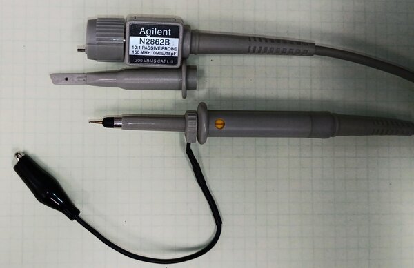
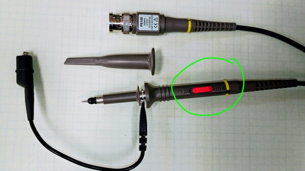
Look again at Figure 4 and the slide switch on the handle. It can be switched to the 1× position or the 10× position. The other probes have permanent 10×` or 10:1 scaling.
This scaling factor is the amount the voltage that is applied to the tip is reduced by the time it reaches the input circuit of the oscilloscope device itself. For example, measuring a 48 V DC power supply with a 10:1 probe means that 4.8 V is sent to the oscilloscope. BUT if the 'scope is configured for a 10:1 probe, it will display a measurement of 48.0 V on the screen, automatically handling the scale factor.
|
Do you see the potential problem when using the probe of Figure 4? Include a little discussion about this, and include some real or imagined (but correct!) examples of what might happen when you don’t keep track of what position the switch is set to. |
2.2. Activities
-
Read the "Getting Started" section.
-
Briefly scan the Appendix A section Oscilloscope Block Diagram and Theory of Operation. High-performance oscilloscopes are some of the most advanced electronic test equipment types — think of building such a device and what instrument you would use to measure internal signals — a … slower 'scope ??
-
Read and work through the instructions of Lab #1 — #6. You may skim #4 and not do the actions, it is FYI for you. Use the printed handout to check off things as you go.
-
As you do oscilloscope actions, do the same actions with your Analog Discovery 3 (AD3) connected to the WaveForms software. It will require a little translation and discovery to do this. WaveForms has many hidden features.
-
Connect your AD3 via USB, open WaveForms, and select the Scope tool.
-
Change a setting in a text box by hovering your mouse over the number and scrolling with the mouse scroll wheel. Much better than clicking-and-select.
-
Grab the 0 V reference or trigger level triangle marks on the left or right sides respectively and move them with your mouse.
Provide evidence that you’ve worked through the lessons by putting screenshots and notes into a Google Doc or MS Word document. Submit a PDF export to Canvas.