πάντα χωρεῖ καὶ οὐδὲν μένει
1. Sending signals over distances
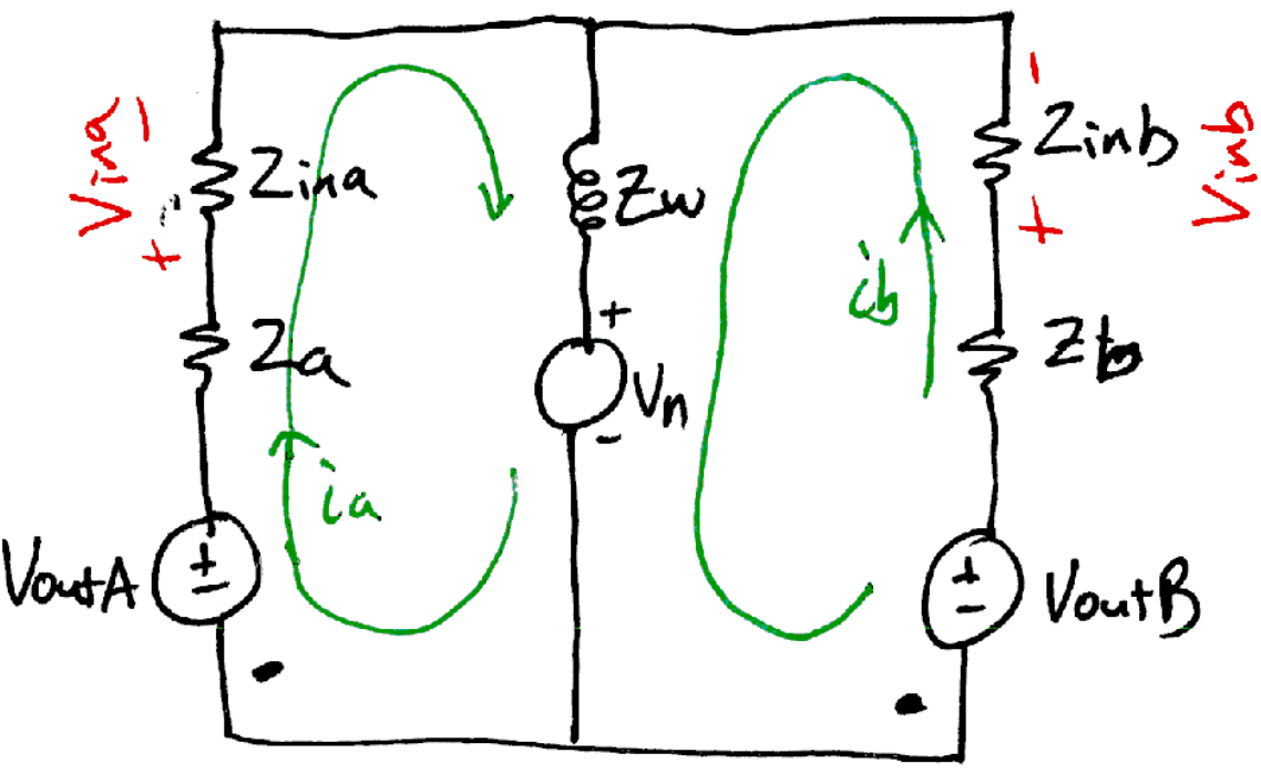
The circuit of Figure 1 represents the core of all signal transmission problems between two circuits. Even when the wires are long enough to be treated as transmission lines.

The driver circuit’s 0 V reference is different from the receiver circuit’s 0 V reference. It is not obvious where to put the Magic Ground Symbol.[2] In fact, you can do the entire circuit analysis without defining one!
1.1. Definitions
Zwire represents the impedance of the "ground wire" connecting the two circuits. Usually this impedance is ignored (to your peril) and the lower line is drawn as a single long “ground node” where the voltage is 0 V all along the line.
vNoise is a superposition of several sources:
-
Changes in the magnetic flux through the enclosed area of the conduction loop induces a voltage around the loop. Faraday’s law of induction - Wikipedia
-
Currents flowing in the wire connecting unrelated other circuits generate a voltage (Zwire × Iother). Introduction to Common Impedance Coupling
| single-ended |
connections have only one loop. Signal a loop is (vout a — Za — Zin a — Zwire — vnoise). Notice how the impedance in the current’s return path is directly in series with the rest of the path. |
| differential |
connections add the (vout b — Zb — Zin b — Zwire — vnoise) path. The signal to be transmitted is set as the difference between the vout a and vout b sources. Let it be known that vout b can be 0 V and not effect the performance. |
|
It is common to make \(v_{out\,b} = -v_{out\,a}\) so that the two output voltages are equal and opposite with reference to the refdrv node. This simply allows the difference voltage to be as large as possible for the given power supply voltage. It increases the signal to noise ratio only slightly.
|
1.2. Circuit analysis
Use mesh analysis to find expressions for the quantities
\(\left(v_{in\,a} - v_{ref,rcv}\right)\) and
\(\left(v_{in\,b} - v_{ref,rcv}\right)\) using KVL.
There are two special cases to consider:
-
\(Z_a \rightarrow 0\)
-
\(\left(Z_a + Z_{in\,a}\right) = \left(Z_b + Z_{in\,b}\right)\)
KVL around ia loop
\(-v_{out\,a} + i_a \left(Z_a + Z_{in\,a}\right) + \left(i_a + i_b\right) Z_w + v_N = 0\)
KVL around ib loop
\(-v_{out\,b} + i_b \left(Z_b + Z_{in\,b}\right) + \left(i_a + i_b\right) Z_w + v_N = 0\)
Next, find the two input voltages
\(v_{in\,a} = i_a \, Z_{in\,a}\)
\(v_{in\,b} = i_b \, Z_{in\,b}\)
1.3. Single-ended case
The driver has only one output terminal voltage, \(v_{out\,a}\), the b circuit is missing, leaving only one loop with all impedances in series.
| \(Z_a\) includes both the driver’s output impedance and the wiring impedance between driver and receiver. |
Draw this circuit.
-
The sign of the noise voltage is irrelevant most of the time since it is almost always uncorrelated with vout a.
What does this equation mean in practical terms?
1.4. Full solution
Including the second b circuit is a little more work to solve. Put into a matrix to solve for the two mesh currents.
Pretty sure you have either tuned out or ran away by now.
1.5. Full solution ft. Superposition
What we really want is the two input voltages vin a and vin b because those are what the signal receiver see.
| Use superposition to find these voltages in response to the three independent sources vout a, vout a, and vN. |
Please switch to day18_notes.pdf starting on page 4.
3. References
More Heraclitus quotes at https://en.wikiquote.org/wiki/Heraclitus