2. BJT modes recap


|
LTspice hot tips
The value of resistor The simulation does a DC sweep ( |
3. Rapid Analysis Objectives
-
Eyeball a circuit and guess the easiest places to begin analyzing.
-
Assumptions ?!
-
What to assume because including more precision doesn’t change numbers much.
-
“Aggressive Ohm’s Law” — avoid using any (or very few) transistor specifics until you’ve found the resistor currents.
-
Ignoring base current is usually a good first step
-
unless a small current at that node makes a difference
-
-
-
You simply need to be fast at circuit analysis fundamentals. At least in setting up the equations. Actually solving them can be tedious.
-
Do you really need the solution to this particular equation?
-
KEEP YOUR EYE ON THE PRIZE
-
This is not abstract art interpretation: “There is a chair in the painting” is what you should observe first --- the obvious stuff.
-
Analyzing something is done for a reason (rarely for the pure joy of the process). Forget the reason and you can lose your way amidst the details.[1]
-

4. Rapid circuit analysis exercise

Quickly find all node voltages and both collector currents in this circuit.
Where do you start?[2]
5. QRP Labs QMX+ radio
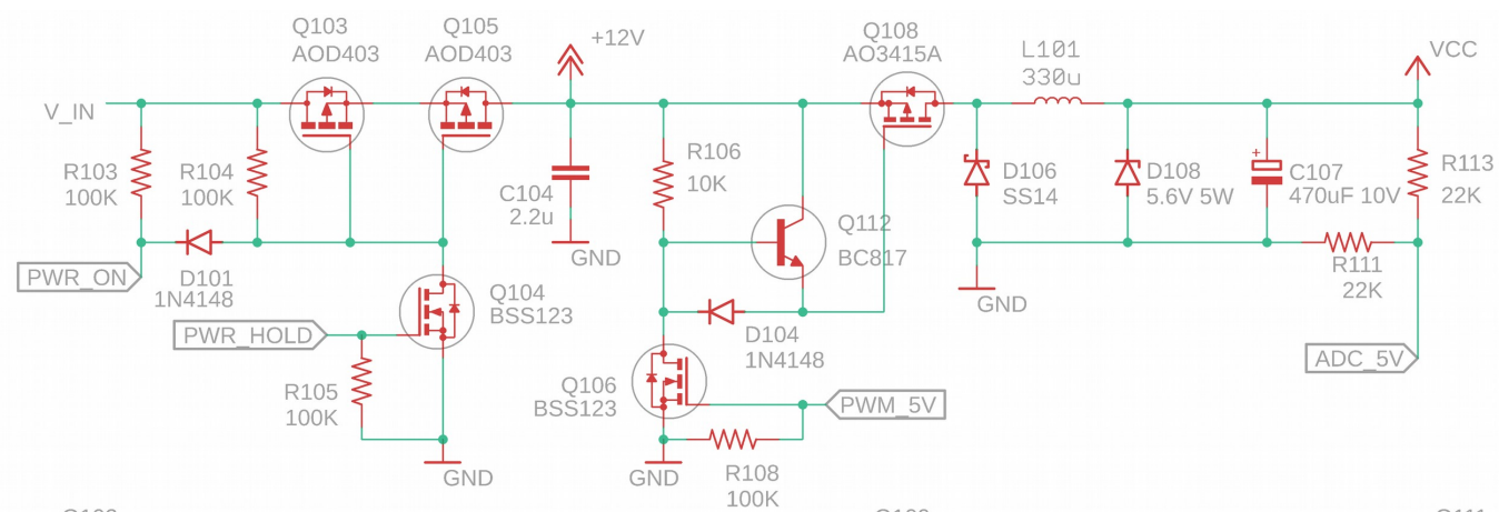
There is a pushbutton switch that can connect PWR_ON to GND which the user presses to initially turn on the device.
PWR_HOLD is an MCU output pin that (especially when there is no power) is initially at 0 V.
PWM_5V also starts at 0 V
-
Combination of Q103 and Q105
-
Effect of grounding
PWR_ONnode -
Releasing
PWR_ONwhenPWR_HOLDis low -
Releasing
PWR_ONifPWR_HOLDis 3.3 V