1. Sony radio amplifier, DC
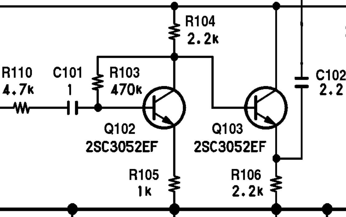
Find the DC bias solution. (Vcc = 8.5 V)
-
Make some assumptions / guesses about transistor parameters.
-
β =
-
VBE =
-
-
It is useful to estimate the range of expected values for the circuit solution
-
IC Q102
-
IC Q103
-
-
Collect KVL and KCL relationships.
After hand calculations, look at the PDF linked at the survey, and take the survey https://forms.gle/A9UhxrwGTCR7CP7m7
1.1. CircuitLab version

Build the amplifier circuit in CircuitLab and use it to check your hand calculations.
-
Do not add the Q103 circuit at first.
-
Then add Q103, how (much) does this change the results?
-
Sweep the \(\beta\) value of
Q102. Predict which aspects of the circuit are most affected by this change, then confirm with the simulation results. What range of \(\beta\) does this circuit require so that everything stays in forward-active mode? -
Simulate the frequency response of this amplifier. What is the voltage gain \(\frac{v_{\mathit{out}}}{v_{\mathit{s}}}\)?
View node X as the output of the Q102 amplifier and the input of the Q103 amplifier groups.
-
Draw the AC equivalent circuit.
-
Draw the small-signal circuit.