1. Estimating ZC and ZE

Use the figure to estimate ZC and ZE.
Then estimate AvØ as a function of frequency for short-circuits between the following nodes. This is the BASS potentiometer at the middle and extreme positions.
-
X → B
-
X → A
-
X → C
Do a similar thing for the TREBLE potentiometer’s middle and extreme positions.
1.1. PM1000 LC filter network
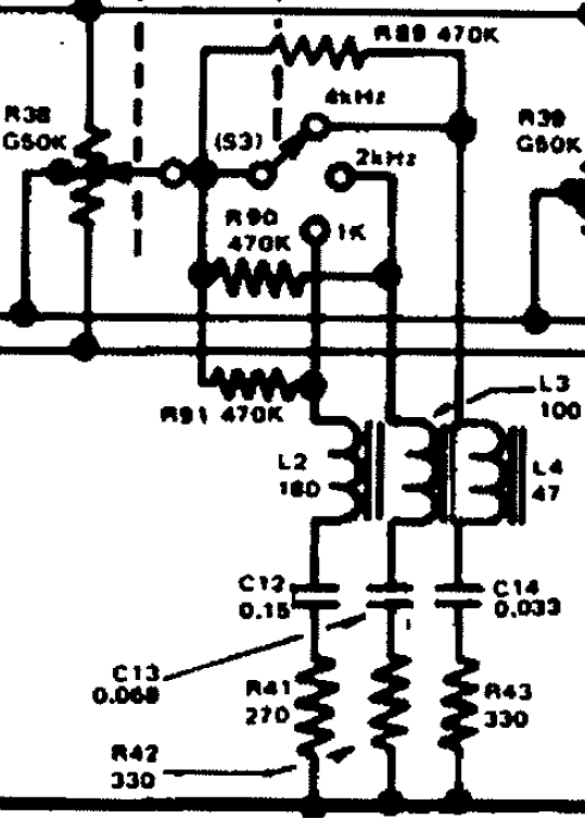
This looks way more complicated simply because most of these parts are attached to a 3-position switch. Leave the switch in the 4 kHz position and redraw the circuit.
Notice how the R89, R90, and R91 470 kΩ resistors bridge the three switch contact positions?
Trace from the R38 potentiometer wiper node on the upper-left and trace the 1 kHz switch position:
R91 is either in the circuit or shorted by the switch.
-
wiper — (R91 or short) — L2 — C12 — R41 — GND
Compare the value of R91 to R41 — a ratio of about 1700:1!