<subtle subtitle>
1. Operational Amplifier Resources
Documents in the course’s docs G-Drive folder about opamps:
-
AN-7: Opamp Applications. 1-page summary of most opamp circuits.
-
AN-A The Monolithic Operational Amplifier- A Tutorial Study - National.pdf
-
A Primer In The Art Of Using Operational Amplifers In General Utility Instrumentation, Morrison 1964
-
Ideal Op Amp Datasheet. If one existed, this would be its datasheet :)
-
Jensen JE-990 opamp paper. Famous discrete-component opamp. This and relatives were used in the major analog recording mixers (“consoles”) of the 1970’s to 2000’s.
-
application-manual-computing_amplifiers.pdf - “Applications Manual for Computing Amplifiers for Modelling, Measuring, Manipulating, and Much Else. containing, in addition to frequent digressions into design philosophy, and numerouse self-serving advisories on equipment selection, a library of practical feedback cirucuits all employing modern Operational Amplifiers — mostly solid state — together with an occasional nostalgic, respectrul, and usefule reference to the not-yet-to-be-dismissed vacuum-tube art.”
^^^ Op amps and control systems/theory go together like apples in a pie.
This is from the company that invented operational amplifiers.
Related topics:
-
augustadt_longitudinal-noise.pdf - Longitudinal Noise in Audio Circuits, Augustadt and Kannenberg, Audio Engineering Society.
A nice discussion about common-mode (“longitudinal”) noise and differential mode analysis. -
1979 Signetics Analog Applications. Tons of analog circuits and great discussion about how they work and are designed.
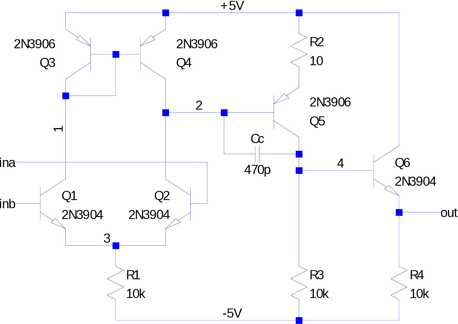
2. Your very own operational amplifier
2.1. Up-Down analysis
Engineers should be good at making quick estimates of behavior and numbers, like where is the decimal point, or mental math with one digit of precision.
The two differential inputs to this operational amplifier are labeled ina and inb, but it is usual to label these two inputs as \(+\) and \(-\) instead. Which pin is which / what is this mapping? First guess: (a guess needs to be checked!)
-
\(in_+\) is node: and \(in_-\) is node:
Next, “simulate” this circuit in your head / on paper to figure out if this ordering is correct or not.
The ideal output of an opamp is: \(v_{out} = A_{v0} \left(in_+ - in_-\right)\)
Three-stage amplifier view:
2.3. Replace with current mirror
Begin with Figure 1 and swap out the differential pair with the emitter-coupled pair from the transistor array.
Then, make a current mirror similar to the mirror from day22 - tail current source.