2022-01-21
1. WinAVR portable tutorial (asm)
| This section is deprecated. Refer to WinAVR Portable and avr_sim Setup instead. |
Nothing wrong with the vendor-provided tools (Atmel, now owned by Microchip), but we want the bare minimum of layers of abstraction and "help" between the text file with code and the actual programs that convert that code into a .hex file to program to the MCU.
WinAVR uses GCC (as does the Arduino platform), but forces allows us to have more control over the compiling process compared to other tools. It is old (2010 version!) … but it works.
The portable version can run from anywhere and does not require installing, which is handy for students.
Local copy (as a .zip instead of .7z) is in the GDrive docs folder:
WinAVR_Portable_V14_1.zip
1.1. Download and setup
Download one of:
-
Local copy (as a
.zipinstead of.7z) in the course’s GDrivedocsfolder: WinAVR_Portable_V14_1.zip
Unzip this archive, then move the folder to a location of your choosing.
Double-click on the file PrepareWinAVRportable.bat and a black cmd.exe window will briefly pop up.
You can move the newly-created shortcut files wherever you would like.
1.2. Optional tweaks
Do some hacking on the software :)
→ these have already been done in the .zip on GDrive. Included here for your learning benefit.
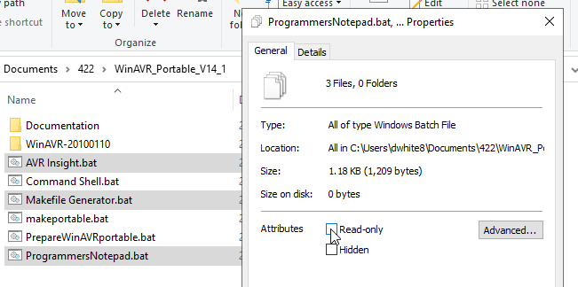
Select these three files
-
ProgrammersNotepad.bat -
Makefile Generator.bat -
AVR Insight.bat
Right-click, select Properties, un-check "Read-only", then OK:
Open these files in a text editor, such as Notepad++.
Add `start "" ` (two double-quotes) to the beginning of the second-to-last lines of each of these files, then save and exit the editor. Example:
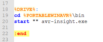
Without these tweaks to the BAT files, the black cmd.exe window will remain visible and closing it will also close the program.
Not a big deal, but also not necessary to keep the window once the main program was launched.
2. avr_sim
Download this ZIP file, then extract the single avr_sim.exe file to a folder
of your choice.
There is no installation, though it will create and update two configuration files within your user’s AppData folder.
avr_sim_25_win64.zip
3. Assembl{y,er} basics
Conventions and features common to most assembly languages and assemblers, with particular focus on the AVR, and avr_sim.
Most assemblers for AVR follow the vendor’s (Microchip) set of features.
-
GDrive docs copy:
AVR_assembler_Microchip.pdf
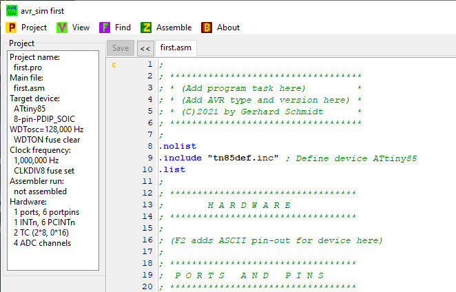
We will begin from the template that avr_sim added with the creation of a new project.
Go ahead and look over this file for a minute and see the syntax and types of items in the file.
…
3.1. Syntax
Each line in the assembly source file has one of the following forms, where “[this is optional]”:
-
[label:] instruction [operands] [comment]
-
[label:] directive [operands] [comment]
-
#preprocessor_directive
-
comment
Preprocessor directives (similar to C) use # as the first non-space character.
Comments begin with semicolon ; and go to the end of the line.
Some assemblers also recognize C-style comments, // line comment and /* block comment / — we will *avoid that style for now.
The documentation for AVR assembler syntax and operation is pretty good, you should use it as a close reference:
3.2. Directives
Only the bare minimum we need for now.
.cseg-
Tells the assembler that what follows is for Program Code (in flash). There is a program code address counter that keeps track of which program address is next.
.org-
Directly sets the address counter to the specified value.
.equ-
Define a symbol to a value.
.equ OCR0A = 0x29
3.4. Labels
Label:-
Word until the first colon
:defines a label. The value of the label is the value of the address counter at this location in the processing.
The following segment defines a code segment that begins at address 0x12ab and contains three instructions.
The rjmp is a relative jump and the assembler computes
The instruction is also at
.cseg
.org 0x0a00

Here:
    rjmp There    ; resolves to rjmp +1
    andi R12, 0   ; address 0x12ac, never gets executed!

There:
    rjmp Here     ; resolves to rjmp -3
3.5. Tasks
-
Open up AVR-instruction-set-manual_2021.pdf and encode the two
rjmpinstructions to their 16-bit object code values.-
Click to check your result
rjmp There→0xC001rjmp Here→0xCFFD
-
Next, paste the example code into avr_sim (replacing the template file completely). Then Assemble the file.
Read the messages in the black window and then click OK to see the listing file .lst.
-
What address is the
rjmp Hereinstruction located at?-
Click to check your answer
0x0A02
-
-
What are the values of the two labels
HereandThere?-
Click to check your answer
Here →
0x0A00There →
0x0A02
-
-
Why does the assembler listing report 3 words for the program size insted of bytes?
-
Click to check your answer
Discuss this with your neighbor! Remember that the AVR uses a Harvard architecture, with separate program and Data (RAM) busses.
-
4. Minimum Blink
4.1. Turn on an LED
First, turn on an LED only.
What needs to happen at a high-level?
-
Setup the port pin to an output.
-
Set the pin high.
Other tasks:
-
Wire up the hardware with an LED+resistor.
-
Program the chip with the
.hexfile containing the code in Flash memory.
According to the ATtiny85_Datasheet.pdf, the instruction at flash 0x0000 needs to be an rjmp to the main code.
(a .cseg and .org and the instruction)
The first 15 words in Flash are the interrupt vectors, so the main code must start after these words in flash.
(another .org to skip to a different location. rjmp to a label!)
First instruction is setting DDRB.