1. Lab preparation
Reminder to watch the videos linked in day06 - §1. Preparation
Become familiar with the content available at RJHcoding.com - AVR Assembly Tutorials.
Notice that we’ve effectively looked at Example Programs #1 and #3 already, though those are intended for the ATmega328P MCU.
Part of the Lab 1 activity has to do with how you create “functions” in assembly, which are called subroutines.
2. Blink differences
Compare the two different toggle-a-pin implementations:
Some major differences to note are
-
16-bit versus 8-bit down counter for the inner loop.
-
Exclusive-OR two registers, then store to
PORTBwith a single delay block versus
Set and clear register bit with two functionally identical delay blocks. -
RJH uses assembly for the
ATmega328Pwhile we are using theATtiny85.
→ Are there any instructions that the 'mega can execute that are not available in the 'tiny?
Figure this out by studying the AVR-instruction-set-manual_2021.pdf.
Section 7.1 Core Descriptions on page 149 and the following Device Tables provide the information about the specific AVR instruction set variants each of these MCUs use.
3. Another branch
sbi/cbi “slow-blink” day06 code to use a different branch instruction (BR__) instead of BREQ.
To better understand what branch instructions do and when they jump versus when they fall through, please read
SR bits
C,
Z, and
S, are especially useful for decision making.
Detecting any result other than zero requires some more work with the CPU.
Changing from the BREQ to a different branch condition requires first setting the appropriate status register bits, then branching on its value.
Instructions for setting SR bits with the result a comparison operation:
-
CP -
CPI
An idea to consider:
-
Setting a register to (256 - x) and then incrementing the register via
incwill overflow in x steps.
4. Subroutines
delay subroutine twice.
From the excellent site RJHcoding.com - AVR Assembly Tutorials, please read:
Instead of using hard-coded constants, use the .equ assembler directive to define symbols for the inner and outer loop iteration counts:
.equ INNER_COUNT = 0xFF  ; 8b unsigned
.equ OUTER_COUNT = 0xFF  ; 8b unsigned

...

Main:
    ; set pin high
    sbi ...
    rcall Delay

    ;set pin low
    cbi ...
    rcall Delay

    rjmp Main


Delay:
    ; <delay code here>
    ret  ;return from subroutine
5. blinkfast
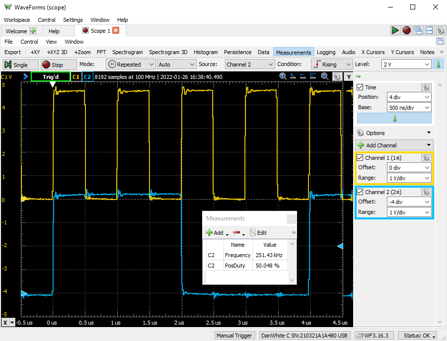
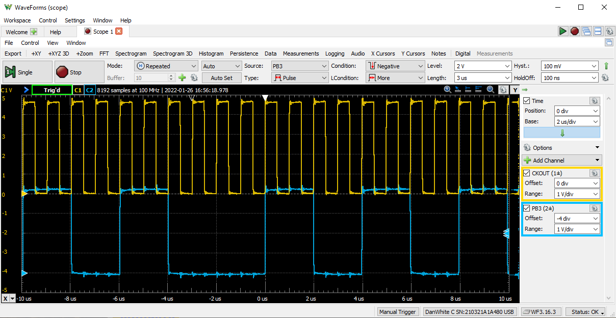
Before you think that the code that pulls off the blistering speed of Figure 1 is perfect, understand that it has one flaw — a glitch every once in a while. The exact periodic interval remains a trade secret since it would give away the solution.
5.1. Special oscilloscope triggering modes
Because the glitch happens less than 0.1% of the time, it can be difficult to actually see or capture.
Enter the many other triggering modes of the Scope in Waveforms (and other nice oscilloscopes).
Consider Figure 2 and see that the low time of PB3 is indeed low for 4 μs, double of the normal 2 μs for a 50% duty-cycle 250 kHz waveform.
The trigger settings are all of the dropdown boxes from Mode: to HoldOff:. Clicking tiny green up-arrow on the right side of this area will collapse the advanced settings, as per the mouse-over text hint.
This particular trigger condition was set up to look for a low (negative) pulse whose duration was more than 3 μs. Determining what is "low" or "high" is set by the level of 2 V with a hysteresis of ±100 mV.