2. Setup
Use the following Waveforms workspace:
| Purpose | Nano | ATtiny85 | AD2 default | Description |
|---|---|---|---|---|
RESET |
D10 |
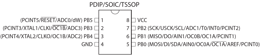
pin 1 |
D1 |
reset |
MOSI |
D11 |
pin 5 |
D0 |
Serial data in |
MISO |
D12 |
pin6 |
D3 |
Serial data out |
SCK |
D13 |
pin 7 |
D2 |
Serial clock |
Program this code to your ATtiny85:
/*----------------------------------------------------------------------*
 * Sleep demo for ATtinyX5.                                             *
 * Wire a button from pin D2 (INT0, PB2, DIP pin 7) to ground.          *
 * Wire an LED with an appropriate dropping resistor from pin           *
 * D4 (PB4, DIP pin 3) to ground.                                       *
 * Pushing the button wakes the MCU.                                    *
 * After waking, the MCU flashes the LED, then waits 10 seconds before  *
 * going back to sleep.                                                 *
 *                                                                      *
 * Jack Christensen 07May2013                                           *
 *                                                                      *
 * Developed with Arduino 1.0.4.                                        *
 * Test conditions for all results below:                               *
 *   5V regulated power supply                                          *
 *   8MHz system clock (internal RC oscillator)                         *
 *   Fuse bytes (L/H/E): 0xE2 / 0xD5 / 0xFF                             *
 *   Arduino-Tiny core, http://code.google.com/p/arduino-tiny/          *
 *                                                                      *
 * Note that only the ATtinyX5 devices below have BOD disable           *
 * functionality implemented. With Vcc=5V, the BOD will draw            *
 * 20-25µA, depending on temperature.                                   *
 *   ATtiny25, revision E, and newer                                    *
 *   ATtiny45, revision D, and newer                                    *
 *   ATtiny85, revision C, and newer                                    *
 *                                                                      *
 * ATtiny45V-10PU, Rev. G                                               *
 *   7.4mA active, 0.1µA power-down.                                    *
 *                                                                      *
 * ATtiny85V-10PU, Rev. B                                               *
 *   7.1mA active, 21µA power-down.                                     *
 *                                                                      *
 * This work is licensed under the Creative Commons Attribution-        *
 * ShareAlike 3.0 Unported License. To view a copy of this license,     *
 * visit http://creativecommons.org/licenses/by-sa/3.0/ or send a       *
 * letter to Creative Commons, 171 Second Street, Suite 300,            *
 * San Francisco, California, 94105, USA.                               *
 *----------------------------------------------------------------------*/

#include <avr/sleep.h>

#define LED 0                      //LED on PB0, DIP pin 5
#define KEEP_RUNNING 10000         //milliseconds


void setup(void)
{
    //to minimize power consumption while sleeping, output pins must not source
    //or sink any current. input pins must have a defined level; a good way to
    //ensure this is to enable the internal pullup resistors.

    for (byte i=0; i<5; i++) {     //make all pins inputs with pullups enabled
        pinMode(i, INPUT);
        digitalWrite(i, HIGH);
    }

    pinMode(LED, OUTPUT);          //make the led pin an output
    digitalWrite(LED, LOW);        //drive it low so it doesn't source current
}


void loop(void)
{
    for (byte i=0; i<5; i++) {     // flash the LED
        digitalWrite(LED, HIGH);
        delay(100);
        digitalWrite(LED, LOW);
        delay(100);
    }
    digitalWrite(LED, HIGH);

    delay(KEEP_RUNNING);           // opportunity to measure active supply current

    digitalWrite(LED, LOW);
    goToSleep();
}


void goToSleep(void)
{
    byte adcsra, mcucr1, mcucr2;

    set_sleep_mode(SLEEP_MODE_PWR_DOWN);
    sleep_enable();
    MCUCR &= ~(_BV(ISC01) | _BV(ISC00));      //INT0 on low level
    GIMSK |= _BV(INT0);                       //enable INT0
    adcsra = ADCSRA;                          //save ADCSRA
    //ADCSRA &= ~_BV(ADEN);                     //disable ADC

    cli();                                    //stop interrupts to ensure the BOD timed sequence executes as required
    mcucr1 = MCUCR | _BV(BODS) | _BV(BODSE);  //turn off the brown-out detector
    mcucr2 = mcucr1 & ~_BV(BODSE);            //if the MCU does not have BOD disable capability,
    MCUCR = mcucr1;                           //  this code has no effect
    MCUCR = mcucr2;
    sei();                                    //ensure interrupts enabled so we can wake up again

    sleep_cpu();                              //go to sleep
    sleep_disable();                          //wake up here
    ADCSRA = adcsra;                          //restore ADCSRA
}

//external interrupt 0 wakes the MCU
ISR(INT0_vect)
{
    GIMSK = 0;                     //disable external interrupts (only need one to wake up)
}
Connections:
-
PB0(pin 5) to an oscilloscope input. -
PB2(pin 7) to a button that connects to GND.
Measure the power supply current of this sketch. Configure the benchtop meter to:
-
Manual range: 10 mA
-
S speed, for the most precision
This current should:
-
Start at about 4.3 mA, then after a few seconds, drops to
-
250 μA
Push the button, or briefly connect the pin to GND. The supply current will jump back up to 4.3 mA and eventually return to 250 μA.
-
Connect
PB1(pin 6) to GND. -
The supply current will increase to 340 μA. This pin has the internal pull-up resistor enabled. What is the effective resistance of this resistor, given this increase in current?
Finally, the Arduino framework enables the ADC even though the chip itself starts with the ADC disabled.
-
UNcomment the line:
ADCSRA &= ~_BV(ADEN); -
Recompile and upload
The sleep mode power supply current will drop to either near zero (need to change the meter’s range to actually measure well), or about 92 μA depending on the state of PB1 (pin 6)'s state.
3. Other
Example code segment from avr-libc for the proper way to sequence shutdown into a sleep mode:
#define SLEEP_MODE_IDLE (0x00<<3)
#define SLEEP_MODE_ADC (0x01<<3)
#define SLEEP_MODE_PWR_DOWN (0x02<<3)

void system_sleep(void) {
    set_sleep_mode(SLEEP_MODE_here);
    cli();
    if (some_condition) {
        sleep_enable();
        sleep_bod_disable();
        sei();
        sleep_cpu();
        sleep_disable();
    }
    sei();
}
4. Reference
avr-libc
https://www.nongnu.org/avr-libc/user-manual/groupavrsleep.html[<avr/sleep.h>: Power Management and Sleep Modes^]