Name:
Honor Code:
Instructions
-
Submit your Concept Map created using the Cmap Cloud tool to Canvas https://canvas.valpo.edu/courses/571/assignments/22756
The remainder of the review is to be completed on paper and submitted at the end of the final exam time.
1. TX line + inverter
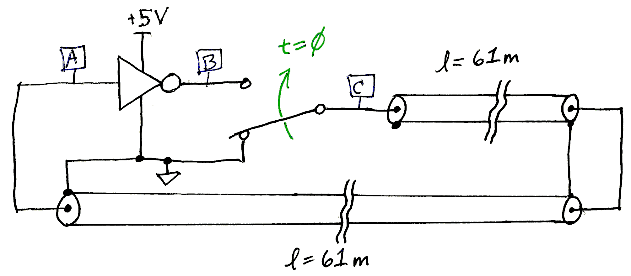
The circuit of Figure 1 represents an inverter attached to a length of coaxial transmission line. The first length of line is routed from the !WIRED Lab to the Antenna Farm on the roof of Gellersen and is directly connected to another length of line from the roof back to the lab. The inverter output connects to a single-pole double-throw switch which is toggled at t=0 from connecting the transmission line to 0 V to connecting the line to the inverter’s output. Before the switch is thrown the initial voltages are:
-
V(A) = 0 V
-
V(B) = 5 V
-
V(C) = 0 V
and immediately after t=0 the voltages are:
-
V(A) = 0 V
-
V(B) = 5 V
-
V(C) = 5 V ←
thus injecting a rising step voltage into one end of the transmission line.
- Assumptions
-
-
The input impedance and the output impedance of the inverter are both matched to the transmission.
-
The transmission line is LMR-600 (datasheet).
-
The connection between the two transmission lines at the roof is properly matched — as if the transmission line is simply 122 m long.
-
1.2. Waveforms
Draw the waveform that would be shown on an oscilloscope with the first channel connected to node A and the second channel to node C.
-
Time should start at just before t=0 and go through 2-3 cycles of the resulting periodic waveform.
-
Label all axes and relevant parts of the waveforms with times and voltages.
-
Clearly mark the cause → effect relationship between the edges. Remember that an oscilloscope displays only what the voltages vs. time are, and doesn’t indicate anything about the cause-effect relationships happening in the measured circuit.
Include a written description of the behavior of this circuit from its steady-state DC condition before t=0 through when it reaches a "steady-state periodic" operating mode.
-
What is the waveform’s duty cycle, period, and repetition frequency?
2. Cat6 Ethernet cable
Consider the Cat6A cable described in the given datasheet: CAT 6A cable (datasheet)
-
Each of the four pairs of conductors in the cable behave like twin lead transmission lines.
-
The specification for Cat6A requires the characteristic impedance Zc of each pair to be 100±15 Ω.
-
The conductors in each pair are 23 AWG solid copper. This is a wire diameter of 0.57 mm.
-
What is the effective relative dielectric constant \(\epsilon_r\) implied by the datasheet’s velocity of propagation in this transmission line?
-
What is the expected wire spacing for this transmission line including the effect of the insulation (dielectric)? Both the wire-to-wire mutual capacitance and the nominal Zc = 100 Ω imply this value — use both of these properties to estimate the wire spacing.
-
(Extra question) Compute the expected propagation delay for a signal to travel 100 m down this transmission line. The propagation delay for this wire is stated as 534 ns / 100 m, which is longer than this result. Comment on this discrepency and why the delay is always longer for twisted pair wire.[1]
3. Current clamp meter
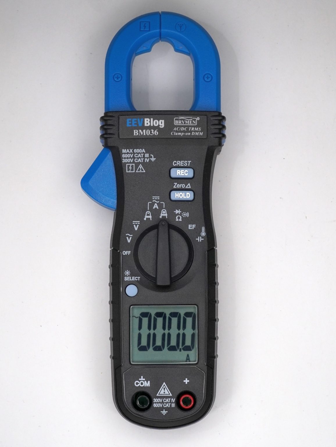
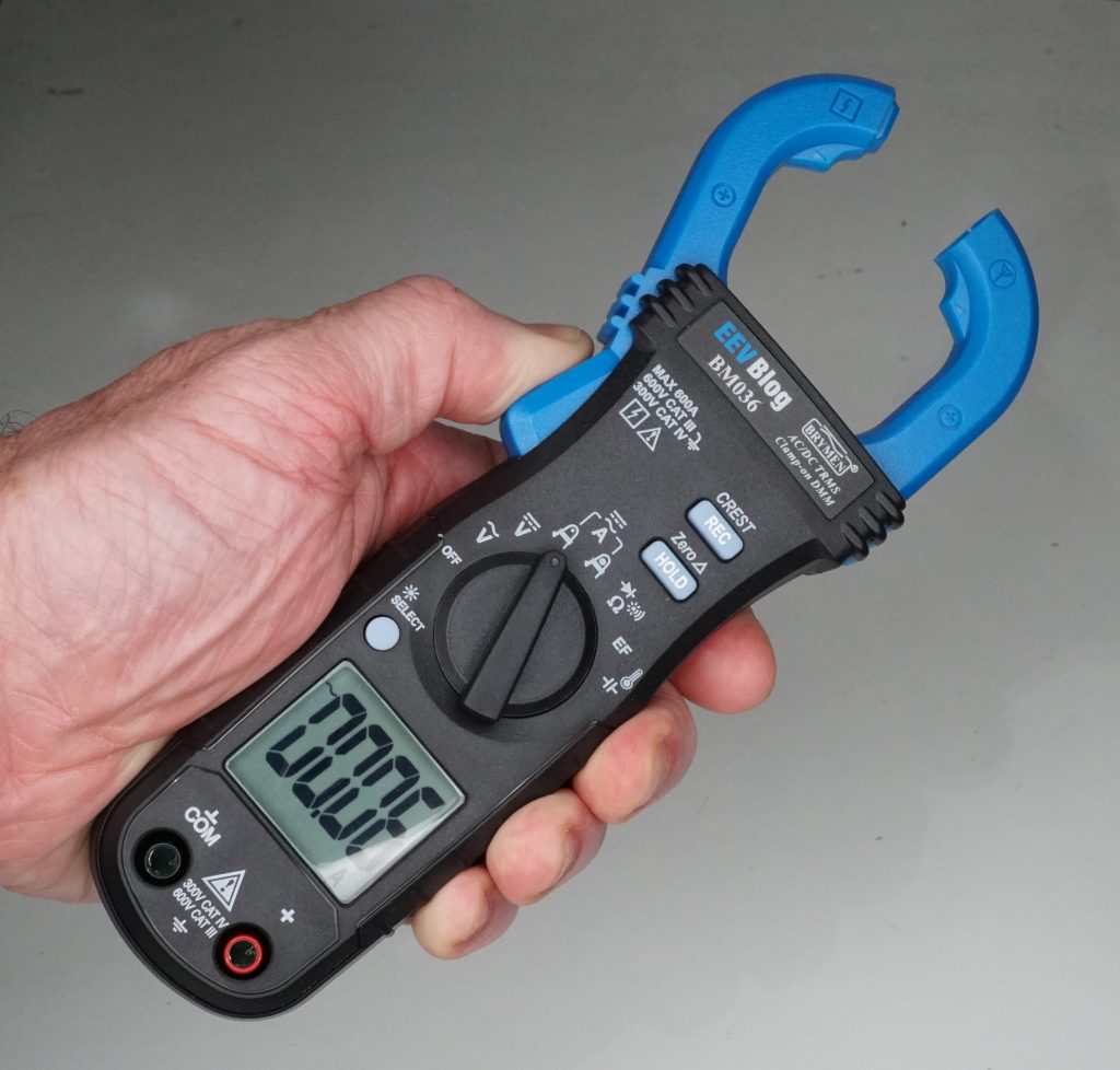
Consider the EEVblog BM036 AC/DC Clamp Meter
In the use case shown, the clamp in opened and then closed around a wire. The meter then displays the current flowing in this wire that is passing through the loop.
| Use very specific terms from the learning objectives from this course in your description. Voltages, currents, electric fields, magnetic fields, physical laws (name and behavior), directions, etc. It will be useful to give an example and work out what the calculations would be. |
-
First assume that the current is varying (AC). Describe how the (or any) device can use electromagnetic principles to detect and measure the mangnitude of this AC current.
-
Next assume that the current is constant (DC). Describe how this (or any) device can measure the magnitude and sign of this current. [2]
4. Quarter wave transmission line
A quarter wave transmission line is frequently used for various purposes including impedance matching tasks. Describe what makes this particular length "special" and why using principles from the course.
6. Antenna area
What is an antenna’s "effective area" Ae ? How is it used and useful in antenna-related calculations?
8. Far afield
Near field and far field are used as conditions on distances away from an antenna. Describe what makes some distance near or far and how it affects the calculations for a given geometrical arrangement of antenna and point of interest.
9. Dipole antenna fields
Describe and draw the electric and magnetic fields around a half-wave dipole antenna. Show the orientation of the fields that radiate away from the antenna relative to the antenna’s geometry.
10. Loop antenna fields
Describe and draw the electric and magnetic fields around a loop antenna with a circumference much shorter than a wavelength. Show the orientation of the fields that radiate away from the antenna relative to the antenna’s geometry.
Segment 4 Learning Objectives
Chapters 28 — 32
- Losses and dispersion
-
-
Calculate the propagation constant, attenuation constant, and phase constant of a lossy transmission line.
-
Write the complete solution for the exponentially decaying sinusoidal voltage for a signal propagating along a lossy transmission line.
-
Design a solution to make a lossy line distortionless.
-
Calculate the electric field, magnetic field, and Poynting vector generated in the far field of an accelerating electric charge.
-
Use the Larmor formula to calculate the power radiating from an accelerating electric charge.
-
- Electric dipole and magnetic loop antenna radiation
-
-
Calculate the electric field, magnetic field, and Poynting vector generated in the far field of an infinitesimal dipole antenna.
-
Calculate the power radiating from an infinitesimal dipole antenna.
-
Explain the significance of a radiation pattern.
-
Calculate the electric field, magnetic field, and Poynting vector in the far-field of a finite dipole antenna.
-
Calculate the electric field, magnetic field, and Poynting vector in the far-field of a small loop antenna.
-
Calculate the magnetic dipole moment of a loop antenna.
-
- Antenna performance metrics
-
-
Calculate or determine the input impedance of an infinitesimal or finite dipole antenna.
-
Estimate the half-power beam width of an antenna from its radiation pattern.
-
Calculate the directivity and gain of an antenna given its HPBW and efficiency.
-
Calculate the effective area of an antenna.
-
Use the Friis equation to find power available at the output terminals of a receiving antenna.
-
- Arrays of antennas
-
-
Determine the radiation pattern for a phased array of a given size, spacing, and phase difference.
-
Determine the voltage that should be applied to each antenna of a binomial array.
-
Determine the radiation pattern for a binomial array of a given size.
-
Determine the directivity of a phased or binomial antenna array.
-
Cohere into a connected whole
Summarize the course’s content so far: Draw a concept map of the terminology, concepts, and connections.
Begin first on paper, brain dumping any words and ideas before you begin to arrange and group them.
-
Examples electronics-world, voltage-current, semiconductor-physics.
-
Use the free tool Cmap Cloud.