1. Introduction
Over 35,000,000,000 (billion!) microcontrollers (MCUs) were manufactured last year. Each MCU is a chip that contains a processor (CPU), RAM for memory, code storage (Flash), and everything else it needs to run programs and interact with the outside world. The processor in your desktop or laptop computer needs an entire motherboard filled with extra chips to make a complete working system.
What makes an MCU so useful is that all of this extra circuitry is included on the same chip as the processor. It doesn’t need any other chips on the board for it to do it’s thing, besides a few bits for supplying power or connecting to large motors or hardware. These extra circuits include useful blocks such as advanced timers to measure or output specific pulses or be alarms or stopwatches, converters to read an analog voltage into a digital number (ADC), digital-to-analog converters (DAC), circuitry to connect to a USB port, talk to other chips, or the Internet, and also WiFi / Bluetooth / NFC or other radios for wireless features. Remember: on. the. same. chip.

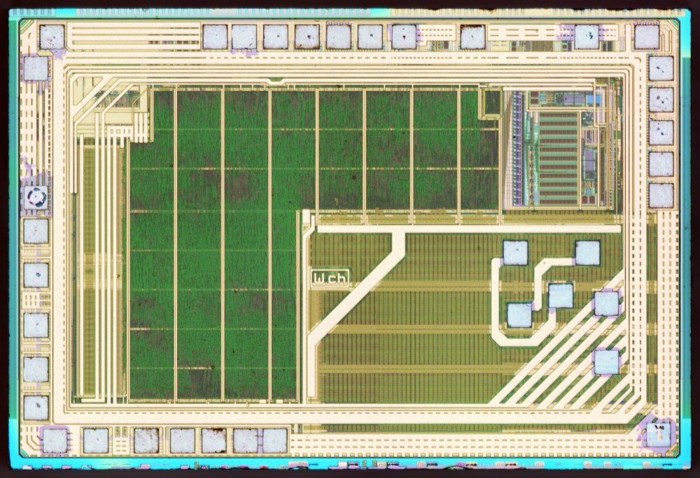
Microcontrollers are both tiny and cheap. Figure 1 shows one of the cheapest MCUs and costs only about 10 cents (!) whose die (the chip itself) is about 1.7 mm wide by 1.2 mm tall. Because of this, they are not nearly as “powerful” as a laptop’s processor. They are instead used for devices which have specific functions. For example, a modern car has 50—200 MCUs in it doing tasks from the dashboard display, the engine and transmission controls, down to even a single tail light sometimes.
Devices using these chips are called embedded systems and are designed and programmed by electrical and computer engineers.
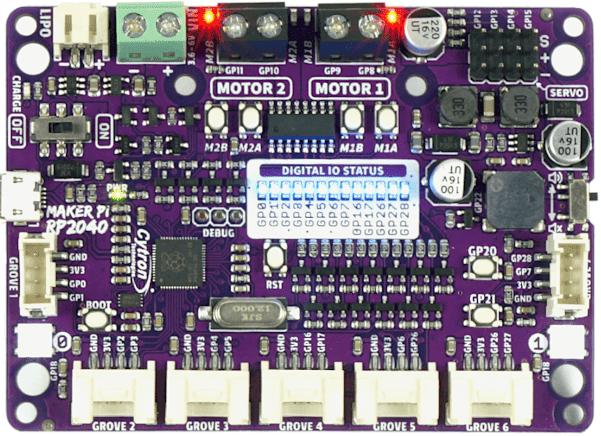
Figure 2 shows a die photo of the much more advanced MCU that is the “brains” on your purple Maker Pi, the RP2040 made by Raspberry Pi. That die is about 2 mm square. Find that chip on your board ([f-makerpi-front]) next to the white “Cytron” printing. The black thing you see is 7 mm square and is the package that contains the chip itself and tiny gold wires that go from the die out to the tiny pins on the bottom edges of the package that are soldered to the printed circuit board.
2. Inventory
Inside the box you received from your visit to Engineering:
-
Maker Pi RP2040 robot controller board
-
Power from USB, lithium battery, or screw terminals, plus charge the battery from USB or DC input.
-
Motor drivers for two DC motors or one stepper motor.
-
RGB LEDs
-
Servo connectors
-
Buzzer speaker
-
Push buttons for user input
-
LEGO pin compatible holes
-
-
USB A to micro cable
-
SG90 servo
-
128 × 64 pixel I2C-connected OLED display module
-
100 mm × 100 mm solar panel, 6 V up to 166 mA current and 1 W power
-
College of Engineering circuit board ruler
3. Thonny install + upgrade
|
Hang tight for a few minutes! Skip this, and you are likely to run into weird problems because your board is running a different version of CircuitPython that the examples assume. You only need to do this install and upgrade once. |
Download and install ![]() Thonny software from thonny.org.
Choose the top option Installer with 64-bit Python 3.10.
Thonny software from thonny.org.
Choose the top option Installer with 64-bit Python 3.10.
Open Thonny and prepare it for connecting to external boards:
-
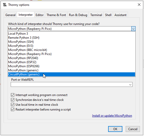
[Menu] Tools → Options →
[tab] Interpreter →
[dropdown] Which kind … ? →
[item] CircuitPython (generic)
The bottom of this tab should now show some links near the OK / Cancel buttons.
-
Click “Install or update CircuitPython (UF2)”. which will do as it says.
Select Cytron Technologies - Maker Pi RP2040 from the list to match the purple board. It may be necessary to exit the Thonny options window and then open it again to refresh the list items.
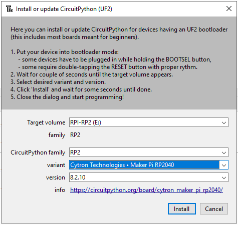
|
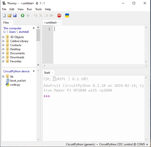
Figure 5 shows version 8.2.10, but will now likely say 9.0.5 or a .6. This is OK, these different versions aren’t different in a way that’s important for this tutorial. You want the newest version that does not say “beta” in the name. |
Close both the Install or update and the Thonny options windows to get back to the main Thonny window.
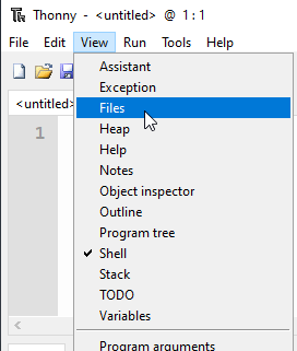
Then get the software ready for the examples by opening the "Files" pane on the left side by:
-
[Menu] View → [check] Files
-
Close Thonny, ensure the board is connected, then re-open Thonny
-
Then turn the board ON using the tiny slide switch next to the USB port.
You now are ready to copy-paste the examples in this activity.
| The stop button is sometimes needed to re-connect with the board. |
4. First example
Find in the Files tab the code.py that is under the CircuitPython device heading.
This lower pane shows the code and other files that are (physically) saved on your board. The upper pane shows files on your computer. FYI, copying files between these two places is easy, but it works a little differently than how the Windows File Explorer behaves.
-
Double-click on the
code.py
5. DC motor
5.1. Manual control
Let’s first play with a DC motor and make it spin without any programming. Remember: a computer just does this really fast, that’s all.
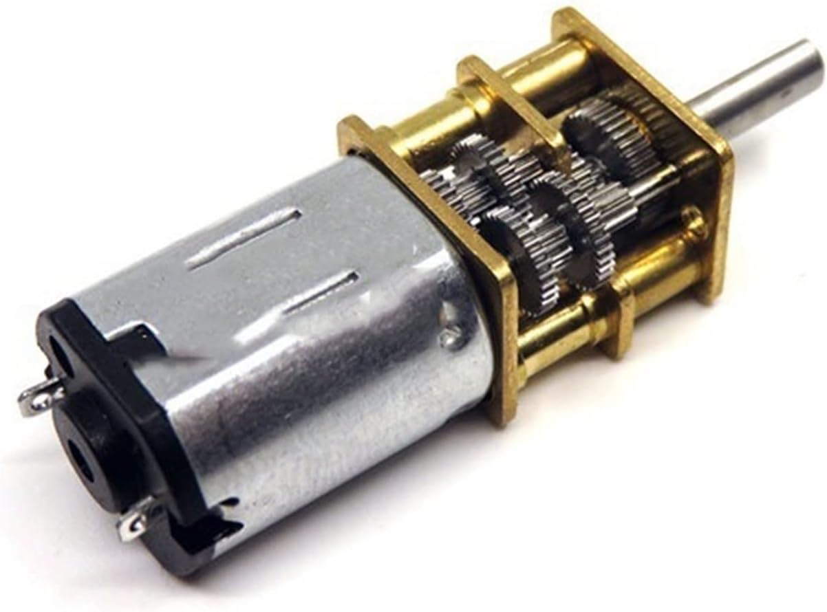
The N20 gear motor is a small DC motor with a gearbox that comes in many variations of gear ratios and output shaft options.
If you have used an electronic door lock and heard the whirring sound it makes when locking, it was likely a variation of this motor inside.
They have a good combination of speed, torque, and size for small robotics projects.
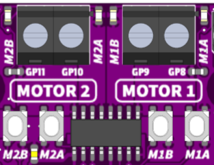
Find the motor terminals and driver chip on your board like in Figure 9. The buttons let us test the motor before we write any code.
-
Push the buttons!
What happens? (click after seeing for yourself)
It jumps when starting and when stopping. This is the effect of Newton’s laws of motion when the motor changes speed suddenly. The twisting is the reaction force (torque) from trying to accelerate the motor rotor’s mass.
-
Push down both
M1BandM1Abuttons at the same time, -
then rock your finger so its only pushing one button to spin the motor.
What is different? (click after seeing for yourself)
It jumps when starting but coasts down instead of stopping suddenly when you push both buttons. Coasting instead of stopping suddenly means much less torque on the motor and so not enough to make it jump.
buttonM1A |
buttonM1B |
pinGP8 |
pinGP9 |
Motor effect |
|---|---|---|---|---|
up |
up |
0 |
0 |
brake / short |
up |
down |
0 |
1 |
forward |
down |
up |
1 |
0 |
backward |
down |
down |
1 |
1 |
coast / open |
You are seeing the difference between short-circuiting the motor (acting like a brake) and disconnecting the motor (letting it slow down with only friction). The motor driver chip has transistor switches inside and the input combinations activate the various operational modes.
-
Look at Table 1 and try out the button combinations again.
In an electric vehicle, stepping on the brake pedal activates the brake mode of the motor controller — it is converting mechanical kinetic energy from the car’s speed back into electrical energy to recharge the battery. Pressing the brake pedal harder will eventually engage the mechanical disc brakes, but it would be a good engineering design if the regenerative braking was used as much as possible.
5.2. Program control
Let’s now “push the buttons” from code instead.
Open ![]() Thonny and connect it to your board.
( follow the live demo )
Thonny and connect it to your board.
( follow the live demo )
| The stop button is sometimes needed to re-connect with the board. |
-
Click the
 icon in the upper-right next to
 PYTHONto copy the code to your clipboard. -
Paste this in Thonny into the
code.pyfile on your board. -
Run the code by clicking the Run current script (F5) play button
from time import sleep
import board
import digitalio as dio

# Setup DC motor pins
M1A = dio.DigitalInOut(board.GP8)
M1A.direction = dio.Direction.OUTPUT

M1B = dio.DigitalInOut(board.GP9)
M1B.direction = dio.Direction.OUTPUT

# Names are better than numbers
BRAKE    = (0, 0)
FORWARD  = (0, 1)
BACKWARD = (1, 0)
COAST    = (1, 1)

# Sequence of things to do
commands = (
    FORWARD,
    BRAKE,
    FORWARD,
    COAST,
    BACKWARD,
    BRAKE,
    BACKWARD,
    COAST,
)

# Do this forever
while True:
    # walk through each of the actions
    for state in commands:
        print(state)

        # set the motor pins
        M1A.value, M1B.value = state

        # wait for a bit
        sleep(0.5)
Take a minute to read this code while watching what the motor does,
-
then change the code to do something a little different and re-run (easy: F5 on your keyboard).
How about just FORWARD, COAST and only sleep for 0.001 seconds?
(first comment out the print(state))
or FORWARD, COAST, COAST?
This is how a speed controller works for a DC motor!
Click for more details about mechanical averaging.
- Mechanical averaging
-
The simple “trick” is applying power to the motor then letting it coast really quickly. Even this small motor can’t speed up much when power is applied for 0.001 seconds, but it still does some. After a bunch of pulses the motor eventually is going at a slower speed that is proportional to the ON time percentage. The rotational inertia of the motor is doing the smoothing of those quick pulses while the electronics are hammering the motor with speedup/slowdown commands.
5.3. Pulse-width modulation PWM
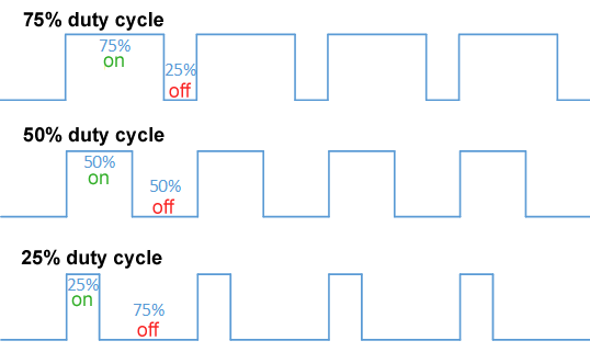
An MCU has special hardware on its chip to easily “blink” pins quickly and evenly without needing to manually bit-bang the pins using code. This extra circuitry, controlled by the processor, is what makes MCUs so incredibly useful.
A common method is to set the high time to a fraction (duty cycle) of the repetition time (period), and is called pulse-width modulation (PWM). Remember: \(\text{frequency} = \frac{1}{\text{period}}\).
Copy ![]() this code into Thonny and run the script.
Push the
this code into Thonny and run the script.
Push the GP20 and GP21 buttons to change the motor’s speed and direction by changing the PWM duty cycle.
from time import sleep
import board
import digitalio as dio

import pwmio
from adafruit_motor import motor

# Initialize buttons as digital inputs
button1 = dio.DigitalInOut(board.GP20)
button1.direction = dio.Direction.INPUT
button2 = dio.DigitalInOut(board.GP21)
button2.direction = dio.Direction.INPUT

# DC motor setup
M1A = pwmio.PWMOut(board.GP8, frequency=1_000)
M1B = pwmio.PWMOut(board.GP9, frequency=1_000)
motor1 = motor.DCMotor(M1A, M1B)

# variables to remember our status
speed = 0
last_speed = speed

# always do this
while True:
    # Read buttons' values and change the speed
    if button1.value == 0:   # button pin is _low_ when pressed!
        speed += 1

    if button2.value == 0:
        speed -= 1

    # what do these do??
    speed = max(speed, -100)
    speed = min(speed, 100)

    if speed != last_speed:  # only update the user if something actually changed
        last_speed = speed
        print(speed)

    # update the motor's speed.
    if speed == 0:
        motor1.throttle = None  # 0 is "brake", None is "coast"
    else:
        motor1.throttle = speed / 100  # need -1.0 to +1.0 instead of a percent

    # Wait before reading the button again
sleep(0.01)-
What happens if you press both input buttons at once? Figure this out from the code and try it out!
Click for more details about the motor noises.
- Screaming motors?
-
Remember how the motor is really speeding up and slowing down quickly and not actually moving at a truly constant speed? This is a physical (change in) motion of a thing about 1,000 times per second — which moves the air around it — which is in the middle of a human’s hearing range ⇒ sound! The varying pulse width changes the number and strength of frequencies of N × 1,000 Hz, which is why the sound changes with the speed. You compute these exactly in a junior-level ECE course.
6. Servo
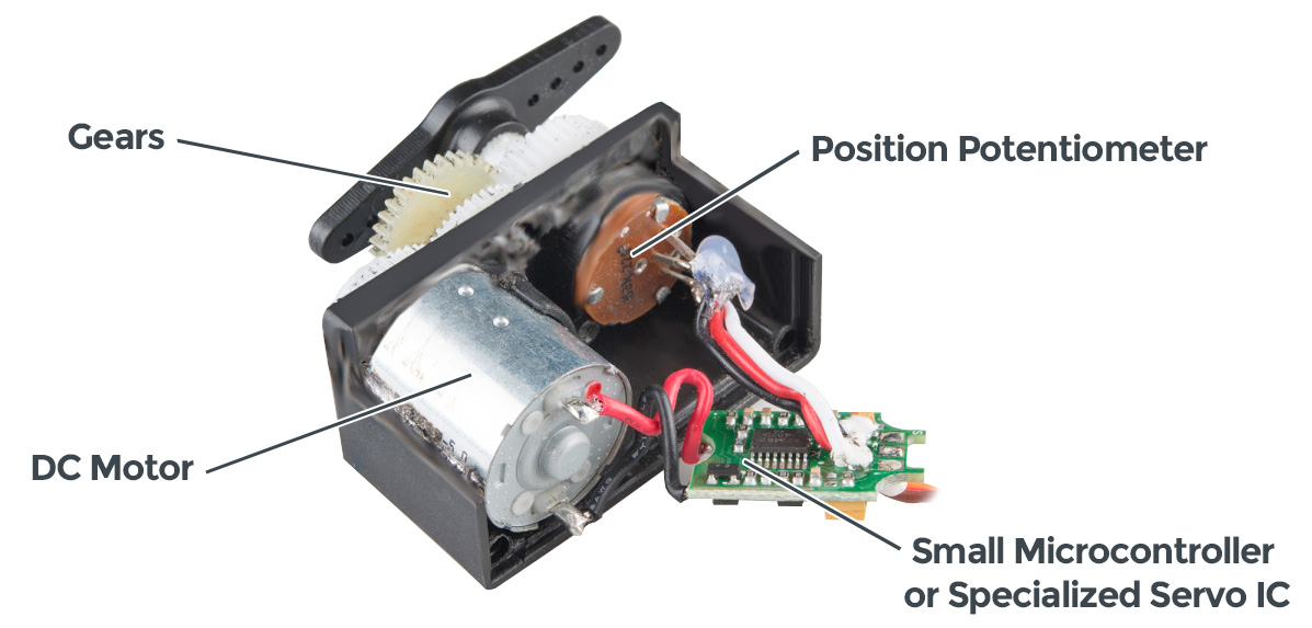

A servo is a combination of a mover and a shaker position sensor with a circuit that figures out how to move to the position commanded at its control input.
They take a specific range of pulse widths at a 50 Hz (1 / 50 = 20 ms) refresh rate.
The Maker Pi board has convenient connectors for 4 servos.
It can handle up to 18 by manually wiring to the GPxx pins if you have some crazy ideas.
from time import sleep
import board
import digitalio as dio

import pwmio
from adafruit_motor import servo

# Initialize buttons as digital input.
button1 = dio.DigitalInOut(board.GP20)
button1.direction = dio.Direction.INPUT
button2 = dio.DigitalInOut(board.GP21)
button2.direction = dio.Direction.INPUT

# Create a PWMOut object on the servo's control pin
# Initialize Servo object.
pwm1 = pwmio.PWMOut(board.GP12, duty_cycle=0, frequency=50)
servo1 = servo.Servo(pwm1, min_pulse=580, max_pulse=2700)

# variables to keep track of things
angle = last_angle = 90

# The Main Event ... loop
while True:
    # Read buttons' values to change the angle.
    if button1.value == 0: angle += 1
    if button2.value == 0: angle -= 1

    # Limit the angle from 0 to 180 degrees.
    angle = max(angle, 0)
    angle = min(angle, 180)

    if angle != last_angle:
        last_angle = angle
        print(angle)

    # Command a new servo angle.
    servo1.angle = angle

    # Delay a bit to allow servo to move.
sleep(0.01)-
Modify the code to move by 5 degree steps instead.
Click for more things to try.
- Servos fight back
-
Try to turn the servo while its powered up and being sent a position command — it fights back with force. What is happening is: you change the angle a little bit → the control chip notices that the actual angle is different from the commanded angle → the chip drives the motor in the direction to fix this error (at full power!).
Remember which way the connector goes and un-plug the servo. Now try to turn the output shaft. The only resistance now is the friction in the gear train to spin the motor. Such a large gear ratio allows a servo to use a small high-speed motor and still provide lots of torque at the output shaft.
7. Everything
Use the two buttons to control both the DC motor speed and servo position. Deal with the fact that the motor library expects numbers {-1.0 … +1.0} while the servo library expects numbers {0 … 180}.
from time import sleep
import board
import digitalio as dio

import pwmio
from adafruit_motor import servo
from adafruit_motor import motor

# Initialize buttons as digital input.
button1 = dio.DigitalInOut(board.GP20)
button2 = dio.DigitalInOut(board.GP21)
button1.direction = button2.direction = dio.Direction.INPUT

# DC motor setup
M1A = pwmio.PWMOut(board.GP8, frequency=1_000)
M1B = pwmio.PWMOut(board.GP9, frequency=1_000)
motor1 = motor.DCMotor(M1A, M1B)

# Create a PWMOut object for the servo's control pin.
# Initialize Servo objects.
pwm1 = pwmio.PWMOut(board.GP12, duty_cycle=0, frequency=50)
servo1 = servo.Servo(pwm1, min_pulse=580, max_pulse=2700)

# variables for housekeeping
angle = last_angle = 90

# why quit when you're having fun!
while True:
    # Read buttons' values.
    if (button1.value == 0): angle += 1
    if (button2.value == 0): angle -= 1

    # Limit the angle from 0 to 180 degrees.
    angle = min(max(angle, 0), 180)

    # Command a new servo angle.
    servo1.angle = angle

    # convert 0..180 angle range to -1.0 to +1.0 motor range
    speed = (angle - 90)/90
    if speed == 0:   # motor speed = 0 is special, so avoid it
        speed = None

    # update the motor's speed
    motor1.throttle = speed

    # Slow down the update rate so the button effect feels reasonable.
sleep(0.01)8. References
8.1. New to CircuitPython?
Read these in order:
CircuitPython is a modification of MicroPython and is great for learning and short programs.
I usually use MicroPython directly because it makes “driving” the advanced details the MCU in ways that make more sense for me as an expert.
The Maker Pi RP2040 board’s documentation helpfully has examples for both.
You can also program the board using the Arduino tools, or even in bare C or C++ for ultimate control of the software and hardware.