2021-10-25
1. Project 3 review
-
Buttons as inputs should be familiar by now. What to do about the bouncing, though?
-
Review day20 - Quadrature rotary encoder waveforms
-
Confused about signals from an encoder? Welcome to
day21!
-
2. Read encoder with AD2
When attaching some hardware to the input of a device, it is wise to know what is safe:
-
Max/min voltages?
-
Equivalent input impedance?
-
What happens when vinput is out of this range? (max source/sink current, i.e. current into / current out of pin)
Since this is pretty much required information that the user needs to know, it is customary for the manufacturer to provide an equivalent input circuit. A competent engineer user should be able to extract the answers to the above questions from that schematic and companion description. The Analog Discovery 2 information is pretty neat, since the relevant documentation describes the exact circuits and has brief explanations about the design decisions:
2.1. Build-and-measure
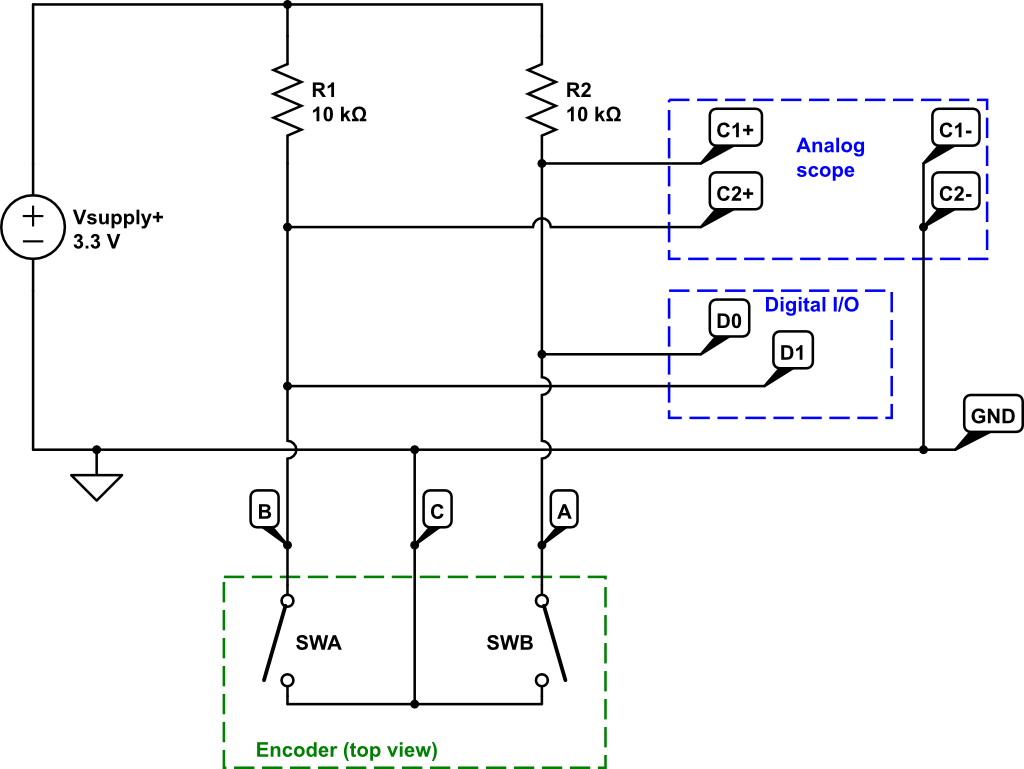
See the figure for how to connect pull-up resistors to your encoder and measure the signals with your AD2. For convenience, use the AD2’s positive power supply output instead of a bench supply.
-
Is this R1,2 value safe for the encoder? It is an easy calculation that will avoid future reliability problems (max contact current is 1mA).
-
See the class time demo for a tip on using your encoder on a solderless prototyping board (breadboard).
Connect your AD2 to a PC and start Waveforms.
-
Start the Scope and Supplies tools. Arrange the windows as you see fit.
The defaults are not quite perfect (IMHO), change these:
-
Position as division: In the Scope, on each of the Time, Channel 1, and Channel 2 settings (gear icon), check this box. The effect is that the 0volts or 0seconds reference triangle stays put even when you change the scale factors.
-
Trigger: (remember that trigger settings are as important as the Time and Channel X settings on an oscilloscope)
-
Mode: Repeated : Normal.
-
Default is "Auto", which will timeout and display when there is no triggering event found.
-
"Normal" mode will only display a waveform when the system finds a trigger event. Switch between Auto and Normal to see the difference in behavior.
-
-
Source: C1
-
Condition: rising (or falling, you will mess with this)
-
Level: Type in a value, or drag the triangle on the right side to change.
-
-
Digital: Select this button along the top row of the Scope window. This is probably the first time you’ve used this, be prepared for the awesomeness of a mixed-signal oscilloscope (analog channels + logic analyzer)
-
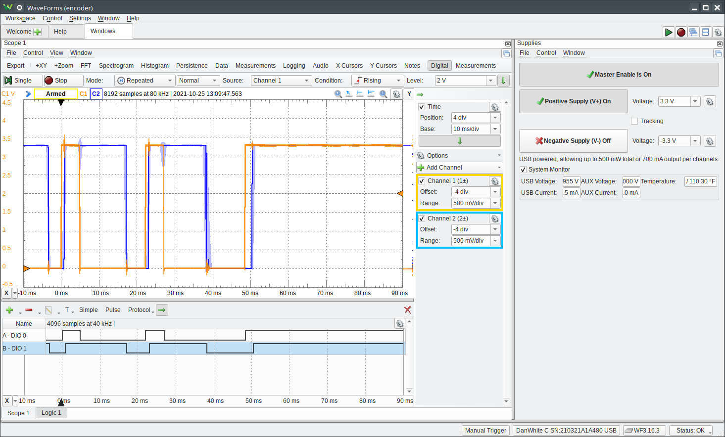
Play around with the Digital sub-window configuration to get it to look like the screenshot.
-
NOTE: you can accidentally change the trigger settings! Conversely, you can trigger the entire system on a digital logic event and see what the analog signals were doing at that same moment ( ! ! ! ) [1]
-
 (the light background is just for printing, no need to change the black background)
With this setup, you should be able to turn your encoder knob and see the A and B signals do their switching squarewave thing.
Just looook at that gnasty bouncing and scraping! This is the Encoder of Caerbannog [2]
Notice that sometimes the Digital inputs also catch the bouncing as multiple transitions.
(turn the knob, look at the signals, change 'scope settings, repeat for a few minutes)
(discuss this in real time with your partner)
-
These are the waveforms that your MCU is seeing.
-
How do you need to read the state of these pins so that the results make sense to the code? [3]
(really do spend brain power thinking about this problem, or else get bit by the rabbit)
3. Drive your servo with AD2
Look up the datasheet (GDrive) for your SG90 servo to get the pinout.
-
Attach the
W1wavegen to the signal (and GND). -
Supply +3.3V power to the servo (+V and GND) from a benchtop power supply.
-
Or, add the AUX power input for your AD2 and power with the AD2 supply.
-
(this only works for 3.3V and not higher due to AD2 supply limitations)
-
Configure Wavegen to output a 50Hz pulse with a high time between 1ms and 2ms.
Turn everything ON, and see the servo respond to the pulse position commands.