Dan White dan.white@valpo.edu
Two-probe device to find low resistance paths with audible output.
Progressive design build and test posts. shortsquawker-1
1. Features
Two probe pins
Button:
-
Hold: zero to current value
-
Press: activate / deactivate alternating ref-meas tone
-
Short press captures current value as reference
-
Tone alternates between live and reference. Or two tones at once?? TBD
-
Tone:
-
Pitch is proportional to resistance
2. Design

2.1. Pin assignments
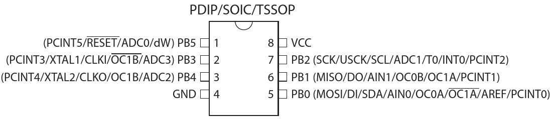
-
PB4: Probe + -
PB3: Probe − -
PB1: Speaker -
PB0: unused (could be speaker −) -
PB2: Button. Active-low, internal pull-up
2.2. Configuration
2.2.3. ADC setup
-
1.1 V reference
-
REFS[2:0] = 0b010, Table 17-3, p.134 -
ADMUX |= 0x80(note random bit order in reg §17.13.1, p.134)
-
-
Unipolar differential with 20x gain, Table 17-4, p.135
-
MUX[3:0] = -
0101PB4 - PB4, ADC 2-2 (self offset) -
0111PB4 - PB3, ADC 2-3 -
ADMUX |= 0x05or0x07
-
-
ADC clock prescaler
-
if
f_cpu = 8 MHz, prescale /64 gives fADC=125 kHz -
ADCPS[2:0] = 0b110 -
ADCSRA |= 0x06
-
-
Disable digital input buffers. §17.13.5, p.138
-
ADC[3:2]D = 1 -
DIDR0 = 0x18
-
This setup gives: 1.1 Vref / 20x / 210 = 53.7 uV per LSb
10.74 mA test current yields 5mOhm per LSb
2.2.4. Timer0 setup
Interrupt every timer overflow as a system tick rate of: 8 MHz / 8 / 256 = 3.906 kHz
This is the PWM update rate, or output sample rate.
This tick updates a digitally-controlled oscillator (DCO), whose phase value is then converted to PWM-generated amplitude of sin() or tri() using a lookup table.
-
Prescale by 8
-
TCCR0B = 0x02
-
-
Enable overflow interrupt
-
**
TIMSK |= (1 << TOIE0)
-