How does the “diode check” mode of a multimeter work?
1. Equivalent circuit
| Page 8: Continuity/diode test |
Uses 0.5 mA±0.2% constant current source |
In this mode, the display shows units of volts until the voltage between the leads is greater than about 1.1 V above which the display shows OPEN.
The open-circuit voltage was measured with a 10 MΩ input resistance meter to be about 2.4 V.

Figure 1 shows a simple equivalent circuit to emulate this behavior.
When the meter leads are not connected to a device, the test current source is forced through the zener diode, which breaks down at 2.4 V.
Since this is larger than the 1.1 V threshold, the meter displays OPEN.
-
What is the largest value of resistance that will cause the meter to display a voltage instead of
OPEN.?
Think first, then click to view the answer
2. Diode check(ing)

| DUT frequently stands for “device under test” |
Given the equivalent circuit, you can see how to interpret the display of a multimeter in this mode.
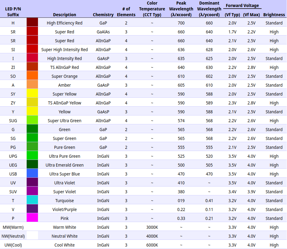
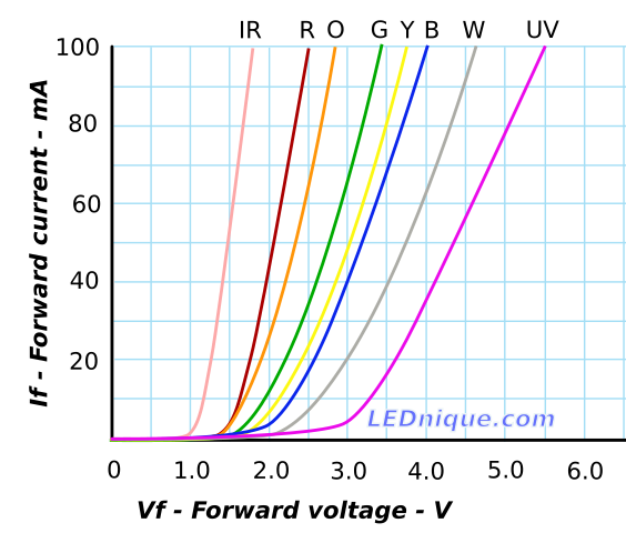
This particular meter will not show the forward voltage of diodes with large forward voltages, such as LEDs.
|
Notice how the forward voltages are inversely proportional to wavelength? The energy of a single photon is \(E = \dfrac{h\, c}{\lambda}\), where h is the Planck constant 6.626×10⁻³⁴ J s. The bandgap of a semiconductor sets the lowest photon energy or longest wavelength (for a direct-bandgap material) of possible. |
What wavelength of photons would silicon emit?
Compute first, then click to check your answer