I before E, except when it’s not
1. Amplifier fundamentals
Please see the Tourbook section of the same name: Tourbook: Amplifier fundamentals
The notation of Table: Symbol capitalization for circuit quantities is a compact representation of the concept
-
¿Why is there no time variable in the \(V_A\) term?
2. AC equivalent circuits

An AC-equivalent circuit only contains the currents and voltages that change.
-
Solve the DC circuit (esp. collector currents). You need these for the small-signal circuit’s numbers.
-
Set all DC Independent sources to zero. (V→short, I→open)
-
Redraw the circuit.
Practice with Figure 1.
3. Large-signal AC
Finding the DC solution of a circuit should be a rather simple concept by now. Construct the circuit equations, add in the constitutive relations (device equations for R, C, L, transistors, etc.), and find the unique solution.[1]
Now, “turn on” the independent sources so they “drive” the circuit. These may vary with time (common), or temperature (never forget), or pressure (it’s true), or other external stimulus. The resulting changes in the node voltages and branch currents (with the DC solution subtracted) is the large-signal (AC) response.
-
if:there are any nonlinear elements in the circuit (i.e. semiconductors), then the exact shapes of these variations depend on the amplitude of the inputs. -
else if:all the elements are linear, then the circuit quantities are simply the superposition of the responses to the independent sources separately. -
else:raise Error("There are only two options.")
4. Small-signal quantities

Consider Figure 3.
-
The black line represents the true relationship between the quantities.
-
The green dot represents the DC solution of a particular circuit.
-
The blue axis represents the AC quantities, or how they change near the average (DC) solution.
-
The red line is tangent to the black curve at the DC operating point. Its slope is simply the derivative of the true equation evaluated at the DC solution.
Zoom in close enough to a small range around the green DC operating point and the true black line appears to be approximately straight.
Approximating the true black line as the red line about the green • point is called
the “small-signal approximation”.
The circuit whose solution is the red line in the blue small-signal coordinate system is the small-signal equivalent circuit.
This circuit is purely linear — containing independent V and I sources, dependent X-controlled Y-sources, Rs, Cs, Ls, and nothing else.
-
What are the SPICE circuit element names used in a linear circuit?
-
Independent sources:
-
Dependent sources:
-
Passive elements:
-
How “small” is small enough?
How much error are you okay with for your particular purpose?
|
Ability to solve linear circuits is a prerequisite for this course
Once we create this s-s equiv. circuit, we are solely in the realm of Linear Circuits 1+2 ECE 263+4, and use the analysis tools from Signals and Systems ECE 360 to switch between the time, frequency, and s domains. |
5. Small-signal equivalent circuits
-
Find the AC equivalent circuit.
-
Decide what to do with any inductors and capacitors. This depends on your frequencies of interest.[2]
-
What are the relative impedances of the L’s and C’s in context.
-
If justified, approximate some of the reactive components as either open- or short-circuits.
-
-
(Redraw the circuit.)
-
Replace each transistor with its small-signal model — either the hybrid-π or the T-model.
Tourbook: §6.4 Small-signal models
5.1. Example: HF-1 microphone amplifier
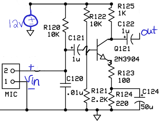
Figure 4 is the microphone amplifier from a radio for voice communications using single-sideband amplitude modulation. The transmitted signal has a bandwidth of about 4 kHz, and so there is little use in keeping frequencies above 4 kHz. Also, voice frequencies below about 200 Hz have little effect on the intelligibility of the received signal and are high-pass filtered out.
-
Step 1: Draw the AC equivalent circuit. See § 2, “AC equivalent circuits”
-
Step 3: Don’t forget to redraw the circuit!
-
Step 4: Replace the transistor with its small-signal (hybrid-π) model. Tourbook: §6.4 Small-signal models
5.2. Why this “impedance about equal” relationship?
Interesting things happen when the real and imaginary parts of an impedance are equal. One of which yields the ubiquitous \(\sqrt{2}\) that shows up all over the place in connection with frequency response. I, personally, prefer to see the quantities as vectors in my mind’s eye, which immediately jumps out as a right triangle with two equal sides.

R and C in series:
R and C in parallel
6. Video worked example
This covers section § 5.1 with its decisions on what to do with all of the capacitors that remain in the AC equivalent circuit.