Practice ⇒ experience ⇒ knowledge
1. Common emitter amplifier

1.1. DC solution
- Given
-
-
Vcc = 10 V
-
Rload = 10 kΩ
-
Rs = 50 Ω
-
- Want
-
-
IC1 = 1 mA
-
VC = 60% of Vcc
-
VE about 1× to 2× the value of VBE
-
- Select
-
-
R1, R2, Rc, Re. Using standard values from the E12 series
The Best Voltage Divider Calculator Ever may be helpful for this task.
-
The rounded R values affect the actual DC solution:
-
VB =
-
IC1 =
-
VC =
-
VE =
Then compute the small-signal transistor values:
-
gm = =
-
rπ = =
-
re = =
-
ro = =
1.2. Small-signal circuit
-
Find the AC equiv circuit
-
Decide what to do with the reactive components. The capacitors don’t have a value, for the purpose here, assume that they are BFCs[1].
Then find the input impedance, output impedance, and (voltage) gain of the small-signal circuit.
2. Complex Ohm’s Law
Using proper names lessens confusion.


By the definitons of impedance and reactance:
BUT
Go back to day10 — Why this “impedance about equal” relationship? and read the section, follow the step-by-step mathematical manipulation to help you remember how to deal with complex numbers.
-
What is the impedance of a capacitor? ZC=
-
What is the impedance of an inductor? ZL=
3. Yamaha PM-1000 Channel Equalizer
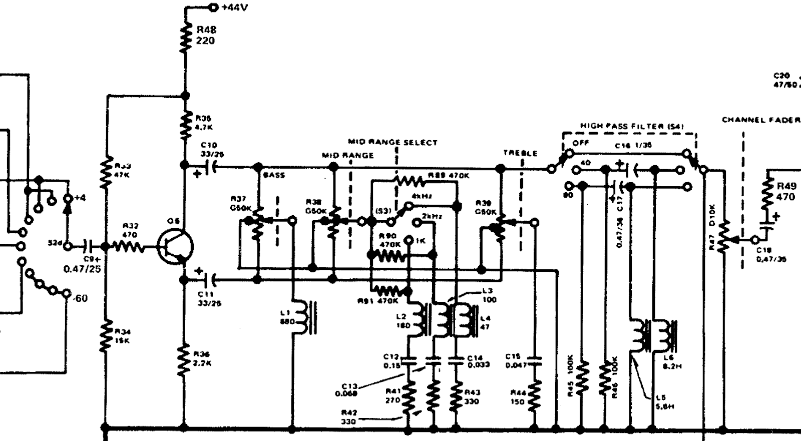
3.1. Step 1a
Draw the AC equivalent circuit.
Pretty easy, you may decide to skip the redrawing part.
3.2. Step 1b
-
Decide a position for each of the two switches Mid range select (S3) and High pass filter (S4). For visual ease, leave them in the same position as the schematic: 4 kHz and OFF.
-
Decide a position for each of the three potentiometers
R37,R38, andR39. → Set them all to the middle position.
3.3. Step 2
Decide what to do with any inductors and capacitors.
-
Capacitors
C9,C10, andC11remain in the circuit. -
What are the frequencies of interest?
As a full-range audio circuit, use 20 Hz — 20 kHz. -
Compute the reactance of these capacitors at the lowest frequency of interest.
Details
The reactance of C10 and C11, even at the lowest frequency of interest, is ten times smaller than the connected resistances.
Make your own decision then click
| Decision: |
Approximate |
Capacitor C9's reactance is close to the value of R34, which forms a high-pass filter with a corner frequency apparently close to 20 Hz.
At higher frequencies, the high(er) signals pass through the filter, meaning C9 has little additional influence.
Make your own decision then click
| Decision: |
Approximate |
3.5. Step 4
Replace the transistor with its small-signal (hybrid-π) model. Tourbook: §6.4 Small-signal models
Then redraw the circuit a final* time.