Analysis non-paralysis
1. Small-signal equivalent circuits
How to draw a circuit’s small-signal equivalent circuit:
-
Find the AC equivalent circuit. (Redraw the circuit.)
-
Replace each transistor with its small-signal model — either the hybrid-π or the T-model.
Tourbook: §6.4 Small-signal models -
Decide what to do with any reactive components. This depends on your frequency range of interest.[1]
-
What are the relative impedances of the L’s and C’s in context.
-
If justified, approximate some of the reactive components as either open- or short-circuits.
-
(Redraw the circuit.)
-
2. HF-1 microphone amplifier
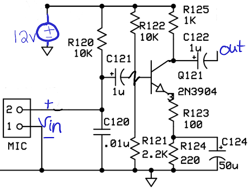
Figure 1 is the microphone amplifier from a radio for voice communications using single-sideband amplitude modulation. The transmitted signal has a bandwidth of about 4 kHz, and so there is little use in keeping frequencies above 4 kHz. Also, voice frequencies below about 200 Hz have little effect on the intelligibility of the received signal and are high-pass filtered out.
-
Step 1: Draw the AC equivalent circuit and redraw.
…
-
Step 2: Replace the transistor with its small-signal (hybrid-π) model. Tourbook: §6.4 Small-signal models
…
-
Step 3: Decide what to do with the four capacitors.
2.1. C124
Consider C124. It’s immediate context is its parallel combination with the 220 Ω R124.
Treating the capacitor as an open- or short-circuit depends on its impedance compared to 220 Ω, then.
From experience with combining impedances in parallel, you now that you can’t ignore one or the other when the impedances are close to each other. Otherwise, if there is a large difference in values, the smaller impedance “wins” or sets the combination’s value.
What frequency is the capacitor’s reactance about 220 Ω?
Compute this yourself first, then check your procedure.
Above this frequency, the capacitor’s impedance (magnitude) is lower, making the parallel combination nearly equal to that small(er) value. At frequencies below this value, the resistor’s impedance is lower. This cross-checks with the fact that, at DC, a capacitor behaves like an open-circuit, leaving only the 220 Ω resistor.
Since we are “interested” in frequencies 200 Hz — 4 kHz, the capacitor always wins and we can ignore R124 (an open-circuit).
At 200 Hz, the lower bound of interest, the capacitive reactance is \(X_C = \left(2\pi\,200\cdot50\!\times\!10^{-6}\right)^{-1} \approx 16\,\mathrm{\Omega}\), which drops to less than 1 Ω at 4 kHz.
This is 16% or less of the series R123.
| Decision: |
Replace |
2.2. C121
From the AC equivalent circuit, the impedance seen to the right → of C121 is \(\left( R_{121} || R_{122} || Z_{in,\,CE} \right)\).
Without more detailed analysis,[3] this is less than 2.2 kΩ
Then, the impedance looking from the (+) node of C121 to the right is simply the sum of the capacitor’s impedance and the impedance to its right.
Write out the expression for this net impedance, then check your result.
This magnitude varies from about 2340 Ω to 2200 Ω over the 200 Hz to 4 kHz frequency range of interest. In other words: not much (6%), meaning the capacitor has little effect when in series. The ultimate does-nothing-when-in-series is a short-circuit.
| Decision: |
Replace |
2.3. C122
Also replace C122 with a short-circuit.
Its purpose is a “coupling capacitor” to block DC and allow the signal to pass to the next stage.
For that role, its impedance should be low (in context) at all relevant signal frequencies.
2.4. C120
Following the pattern, you may be tempted to also declare this capacitor as behaving like a short-circuit.
Go ahead and replace C120 with a short and see how much signal makes it into the amplifier formed around Q121.
Details
Yeah, not much. This is where you also notice that its value is 100× smaller than the other capacitors.
In order to speed up the present discussion, notice that as the signal frequency increases, C120 shorts out more of the incoming signal.
This behavior lets low frequencies pass and blocks high frequencies.
A British engineer would call this a “high-cut filter,” which, after a moment’s thought, is the same as saying a “low-pass filter.”
This passing or cutting action occurs at the upper end of the frequencies of interest. For now, just presume that this is near or above 4 kHz. Therefore, at frequencies lower than this knee, the capacitor has little influence on the circuit’s response.
| Decision: |
Replace |
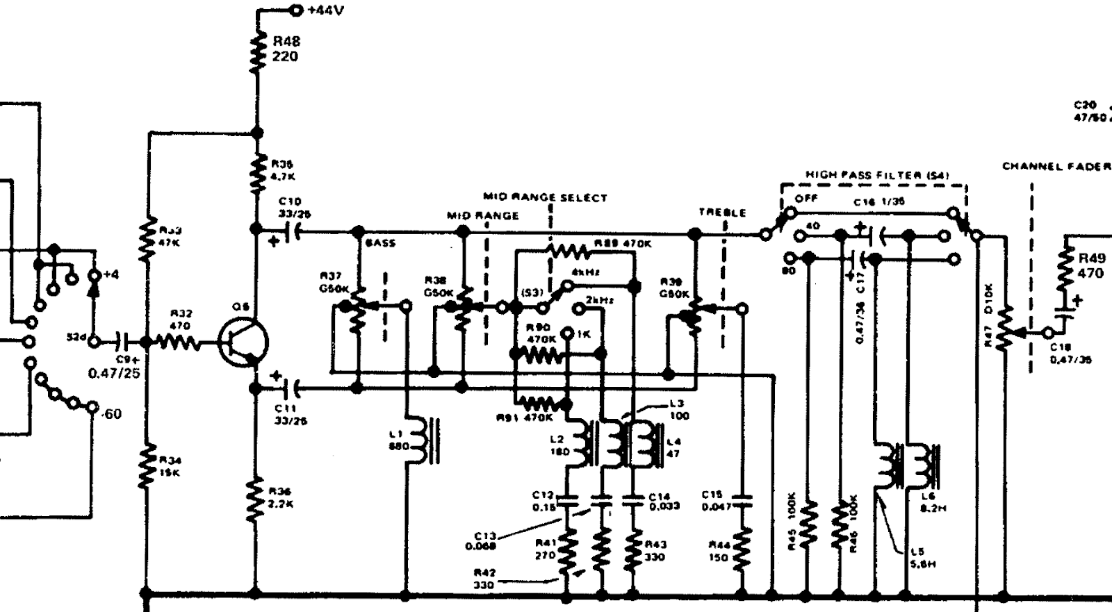
3. Yamaha PM-1000 Channel Equalizer
3.1. Step 1a
Draw the AC equivalent circuit.
Pretty easy, you may decide to skip the redrawing part.
3.2. Step 1b
-
Decide a position for each of the two switches Mid range select (S3) and High pass filter (S4). For visual ease, leave them in the same position as the schematic: 4 kHz and OFF.
-
Decide a position for each of the three potentiometers
R37,R38, andR39. → Set them all to the middle position.
3.3. Step 2
Replace the transistor with its small-signal (hybrid-π) model and redraw. Tourbook: §6.4 Small-signal models
3.4. Step 3
Decide what to do with any inductors and capacitors.
-
Capacitors
C9,C10, andC11remain in the circuit. -
What are the frequencies of interest?
As a full-range audio circuit, use 20 Hz — 20 kHz. -
Compute the reactance of these capacitors at the lowest frequency of interest.
Details
The reactance of C10 and C11, even at the lowest frequency of interest, is ten times smaller than the connected resistances.
Make your own decision then click
| Decision: |
Approximate |
Capacitor C9's reactance is close to the value of R34, which forms a high-pass filter with a corner frequency apparently close to 20 Hz.
At higher frequencies, the high(er) signals pass through the filter, meaning C9 has little additional influence.
Make your own decision then click
| Decision: |
Approximate |
4. Watch these videos
Consider this homework or study time or whatever it takes to do your end of the learning process. Common-emitter amplifier circuit day11:
-
Video: Small-signal analysis of a common-emitter amplifier - part 1
-
Video: Analysis-by-table of a common-emitter amplifier - part 2
-
This covers section day10: HF-1 microphone amplifier with its decisions on what to do with all of the capacitors that remain in the AC equivalent circuit: Video: Drawing a small-signal equivalent circuit.
Because these examples are captured in videos for your reviewing convenience, we get to move on to another example of the process!
5. Amplifier analysis by table lookup
You know the important role that tables of Laplace transforms play(ed) in your life?
-
Identify which type of single-transistor amplifier is in use for each transistor in the circuit. Sometimes the answer is none of the above.
-
Use Tourbook: Table “Bipolar single-transistor amplifier types”, its parameter definitions in the previous table, and the hints in the following figures to identify the Zx impedance terms.
-
Redraw the circuit as a generic amplifier block with input impedance, gain, and output impedance.
-
Compute (numerically, or leave as symbols) the transistor amplifier stage’s Zi, Zo, and AvØ.
-
Done!
6. One Model to Rule Them All

Any linear amplifier can be characterized as:[6]
-
Input impedance
-
Output impedance
-
Gain. There are four options:
-
AvØ = vout / vin. Voltage gain
-
AiØ = iout / iin. Current gain
-
GmØ = iout / vin. Transconductance
-
ZmØ = vout / iin. Transimpedance
-

All of the models in Figure 3 behave identically from the perspective both of the Source and Load.
| The second model with the VCCS has a negative sign. This because of the graphical limitation in the schematic drawing — the output current goes out, or clockwise, to keep the signs consistent across the four models. |


