op amps are great, but they’re not perfect
1. note
Observation about the circuit analysis algebra from the end of (next time’s) day25. When analyzing a circuit with reactive components, it is helpful to know what to expect about the transfer function’s form. In general:
-
If there are N reactive components, then
-
the transfer function will have Nth-order polynomials in s for the numerator and denominator.
→ Example: 3 capacitors + 0 inductors = 3rd-order polynomials
2. Operational amplifer DC errors
2.1. Review and ideal version
The textbook used for (my version of) ECE 264 (syllabus) is pretty decent, and intentionally zero cost from the authors. Its Chapter 4 on Operational Amplifiers is pretty good for an introduction and review.
-
Circuit-Analysis-and-Design_Ulaby-Maharbiz-Furse.pdf ← this PDF version has proper and complete PDF bookmarks for easy navigation. Go directly to the Summary page (pdf page 249 / book page 235).
Download and save to your personal PDF library.
The properties of an ideal op amp are:
-
Infinite input resistance.
-
Infinite gain.
-
Zero output resistance.
which then imply the following identities for circuit analysis:
-
zero input current into each pin
-
\(v_+ = v_-\) [1]
| You should have studied ideal op amps some in ECE 264, but it will be worth your time to read through Chapter 4 of the Ulaby book. |
2.2. DC errors
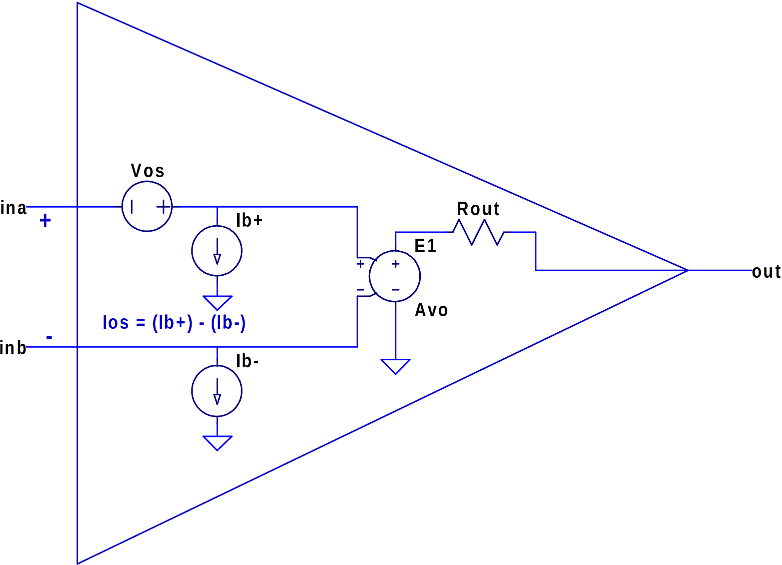
Figure 1 shows a schematic version of how these datasheet parameters affect the circuit’s behavior.
The major DC errors in a real op amp are:
-
Input offset voltage (Vos)
-
Input bias current (Ib)
-
Input offset current (Ios)
Plus transfer function terms (at 0 Hz or DC):
-
Open-circuit voltage gain (Av0)
-
Output impedance (Rout)
Use the circuits of Figure 2 and your measurements from Lab 5 to figure out these parameters for your op amp.
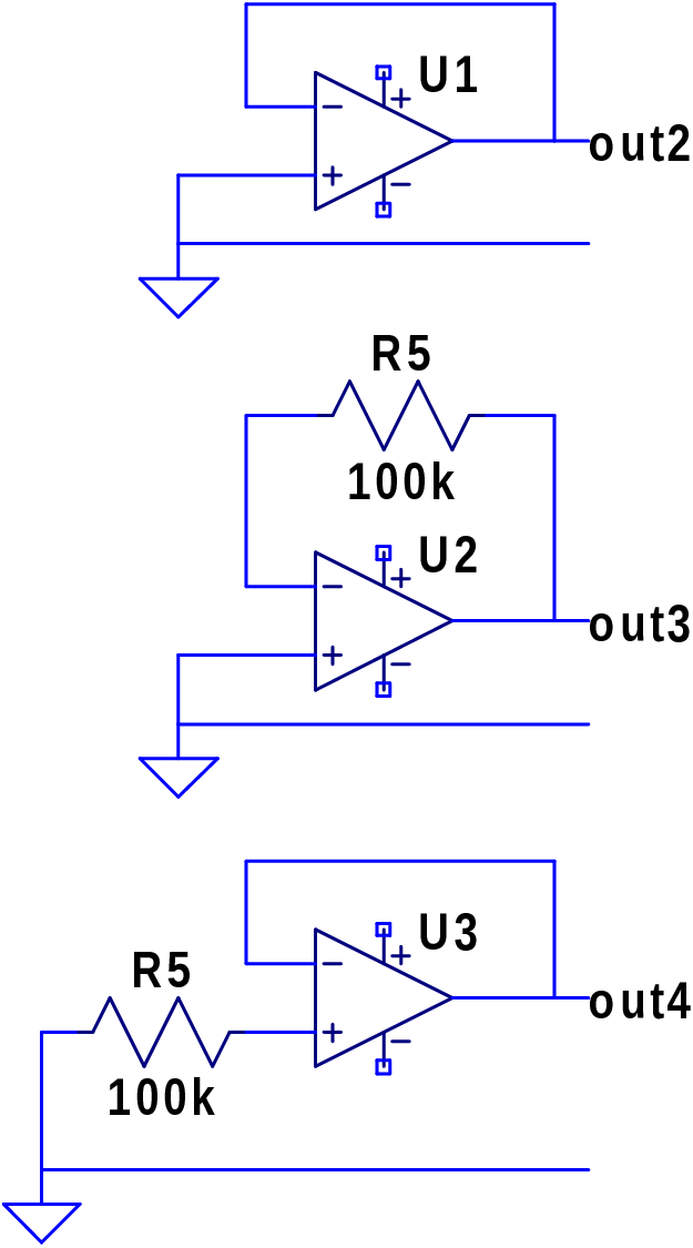
In Lab 5 you made an operational amplifier, pretty neat! The wacky circuits with the 100k resistor? They help you measure most of the major opamp parameters.
Find V(out2) using symbolic (linear) circuit analysis:
Find V(out3) using symbolic (linear) circuit analysis:
Find V(out4) using symbolic (linear) circuit analysis: