1. Course topics
Recent
-
Real-time operating system ideas.
-
Tasks and scheduling.
-
Communicating between tasks. Queue for data, Mutex for sharing a resource (hardware), Semaphore for sharing things.
-
FreeRTOS on the ESP32 devboard
-
-
Measuring power supply current.
-
Sleep mode is tricky because it can be dominated by all the parts attached to the MCU instead of the CPU’s datasheet sleep current value.
-
Pull-up resistors can be hidden sources of supply current use.
-
2. Final project
How can you demonstrate this?
Best way (of many possible options) is to design and demonstrate a system that:
-
Utilizes an RTOS to manage several non-trivial tasks.
-
Seeks to minimize power consumption when the system doesn’t need to use power.
-
Uses a function or two written in assembly that is critical to some important metric, such as timing, power usage, or execution efficiency.
-
Uses hardware that you’ve not had much prior experience with.
2.1. Homework: Set your requirements
Your first task is to consider some project ideas, then create a set of Requirements for your project that would successfully demonstrate your achievement of each of the six Goals.
The ECE 322 final project has a specified set of requirements. This course, like real engineering projects, don’t always have technical, detailed, specifications given to the design team — it is also part of the team’s job to figure out what details support the product’s goals.
Some resources related to writing requirements:
-
Read through a slide desk from Intel about the Easy Approach to Requirements Syntax (EARS)
-
After reading about EARS, this EARS quick reference sheet may be a useful summary.
-
QRA: 21 Tips for Writing Exceptionally Clear Requirements also includes a short summary of EARS as Tip #11 on pdf page 7.
2.2. Suggested project ideas
These are as ideas only, you can do something else that you find more interesting. The final project requirement for the course is that your project demonstrates your learning of course content.
2.2.1. SMART Response XE
-
Write a better driver for interacting with the LCD display that improves some metric.
-
Write and use a library of code that allows two SRXEs to wirelessly communicate using their built-in packet radio. Perhaps a chat application.
-
Make the power button both wake up the system AND put it to sleep. Recall that the BASIC interpreter example requires using the
byecommand to go into sleep mode.
2.2.2. ShortSquawker
-
"Finish" the ShortSquawker to go to sleep as much as possible and minimize the battery usage. Then put it into a box and be battery powered.
-
Implement SS with all of its features on a different MCU.
-
MSP430 is capable of much lower active mode supply current.
-
ATmega329P (Nano board) that can be either battery powered, or, when attached by USB to a PC then it outputs CSV-formatted data to the serial port.
-
2.2.3. ESP32
Port exp32-ble-scan-mqtt application to properly use FreeRTOS.
This is the application that runs on the WIRED Lab’s BluetoothLE sniffer/trackers.
-
Handle operational state changes depending on the availability of a WiFi connection.
-
Save data to a micro-SD card and do the data upload in bursts to save power when the unit is powered by a battery.
Implement ShortSquawker using the ESP32.
Use sleep modes!
Program the ULP processor that is in the ESP32 to manage part of the (ShortSquawker, other) application to avoid waking up the main processor(s) to save power.
2.2.4. Other hardware
-
Write a driver to display text and other characters to this device.
-
A bar graph "level meter" would be pretty neat.
-
Use as the display for ShortSquawker, or to display ADC or other readings.
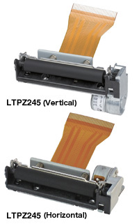
LTPZ245R-C384_thermal-printer_G21008.pdf Thermal receipt printer mechanism.
-
Write a driver to print pixels to paper.
-
The core part of this is writing to the print head’s shift register. The part has very few digital features.
-
-
Handle the timing to drive the paper-drive stepper motor.
-
Modify the print speed and pixel ON (heater) time for best print quality. The manual has all of this information.
-
Accept via an input (UART, Bluetooth, ???) each line of 384 pixels to print. Perhaps a line of 40 hex values:
c0ffee…\n -
Use a simple font to print incoming text.
-
Include some commands to advance/retract the paper for loading new paper or helping the user tear off the printed part?
This project requires creating a very simple PCB to breakout the connector pins out to 0.1-inch header pins. This can be fabricated using the CoE’s laser cutter.
2.2.5. Other ideas
The lists are not inclusive in terms of the types of things you can build that demonstrate your knowledge and skills with respect to the Goals!
Make something that is useful or interesting to you.
Seek advice on how much time or effort certain aspects of your project may involve. You’re not necessarily expected to be able to make such an estimate — it requires experience.
2.3. What’s all this "Demonstrate a Goal" stuff anyhow?
An homage to the legendary /rap/ Bob Pease.[1]
| First, review The Requirement. |
Next, consider which Goals are touched on within your Lab 1—3 report document:
Given this implied contents of Report 1, what have you not yet demonstrated via a form that you can show to others? Consider each Goal in turn:
2.3.1. G-HWSW
Design, document, and demonstrate systems that combine dedicated hardware and software to complete a specific task.
Though Lab 3 focused on the code, it still required external circuitry to function.
Short. Squawker.
2.3.2. G-PWR
Create microcontroller programs that conserve energy by effectively using low-power modes.
The activity of Lab 6 was specifically focused on measuring the power supply current of an MCU.
Power and energy was the main topic of class times:
Recognize that “low” in low power is an adjective that refers to a relative number. → “Low” compared to what?
Demonstrating that your system is low power requires you to make a comparison to some similar (same functionality) system that uses more power. Because the power supply voltage is usually fixed, we use power supply current as a proxy for power usage.
-
Measure your system’s supply current before and after adding (or turning on via a
#define) sleep modes and other optimizations.
2.3.3. G-RTOS
Design and implement a basic kernel for a real-time operating system.
We used the zyBook path to a task scheduler as a framework to introduce the core function of an RTOS, task scheduling. Then we looked at resources from and about FreeRTOS.
Lab 5 directly used FreeRTOS, as conveniently included in the Arduino board package for the ESP32, to experimentally learn about how to create tasks and structure a task-based system architecture.
The original Arduino sketch version of ShortSquawker already implemented several RTOS-task-like activities, several class times discussed this.
Natural task segmentation can be:
-
User input handling
-
Core functionality — a high priority
-
Data processing
-
Background “housekeeping” activities.
-
Demonstrating something related to an RTOS therefore requires a system that has several tasks that run periodically or occasionally to support its functionality and features.
2.3.4. G-NEW
Demonstrate an ability to adapt to new technologies/platforms in a rapidly changing field by
Developing embedded solutions that operate with different/new pieces of hardware (such as sensors, actuators, communication devices)
Developing embedded solutions with more than one CPU architectures/microcontroller families
It is a weak argument that a final project which involves (only) the ATtiny85 achieves or demonstrates any aspect of this Goal.
|
Lab 4 specifically dealt with a new architecture in direct engagement with #2.
Everyone has a SMART Response XE device, which contains lots of new-to-you hardware. Though the CPU uses the AVR architecture, the rest of the system is new — you’ve yet to directly work with a MCU chip that includes an integrated radio for wireless communication.
There are other infrared remotes, the blue ones from ECE 322, that would be nice platforms for accepting user commands. IR receiver modules are on-hand, in-stock, and available to use.
Using the ESP32 devboard for some project is also a great option!
Remember that this device requires a 3.3 V power supply voltage — the reason that USB-powering works is the devboard has a linear voltage regulator (an AMS1117 in this case) that accepts the 5 V from USB and outputs a stable 3.3 V.
3. Other
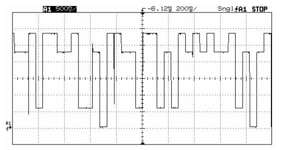
This is a super simple (and neat!) trick. An R-2R digital-to-analog converter can output the value of a set of port pins and convert to a proportional voltage. Viewed on an oscilloscope, the voltage then is a time series of whataver the value represents. In the figure, it is the currently-executing task in the RTOS.